Breadboard games. Christmas 2023

This event’s focus is not so much on delivering a finished game as delivering a platform for learning micropython.

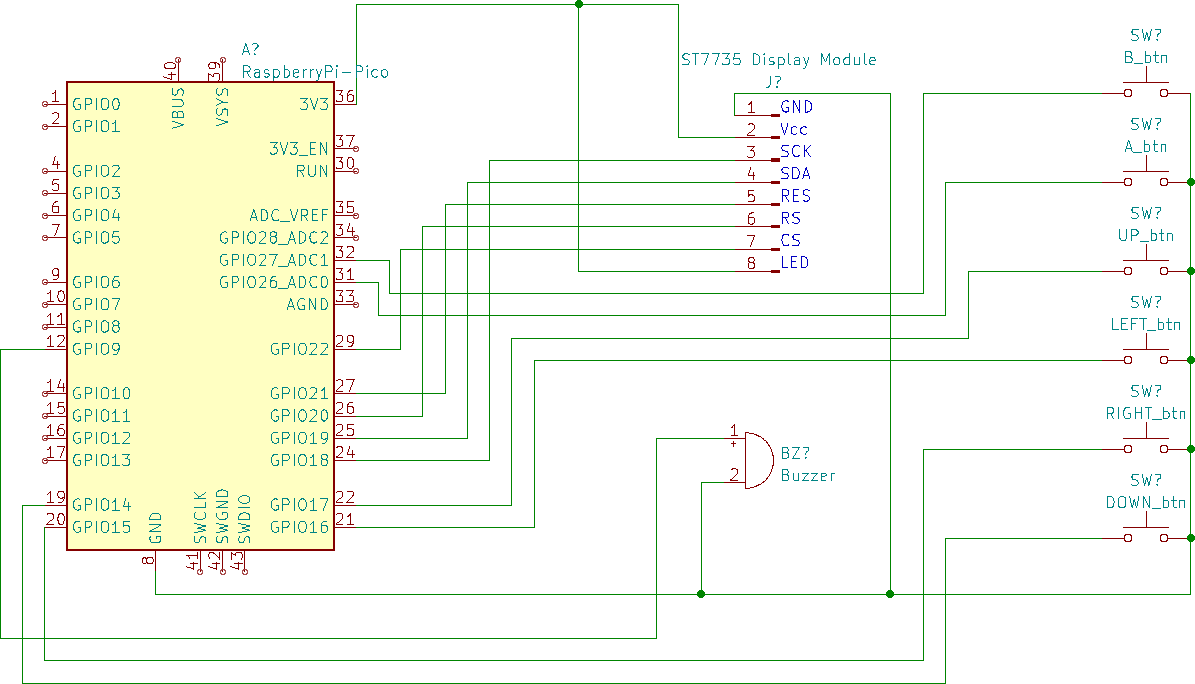
The board consists of a SeedStudio/Xiao RPI2040 which has just enough pins for this project. It also has a built-in WS2812 RGB Led along with additional LED’s on board.

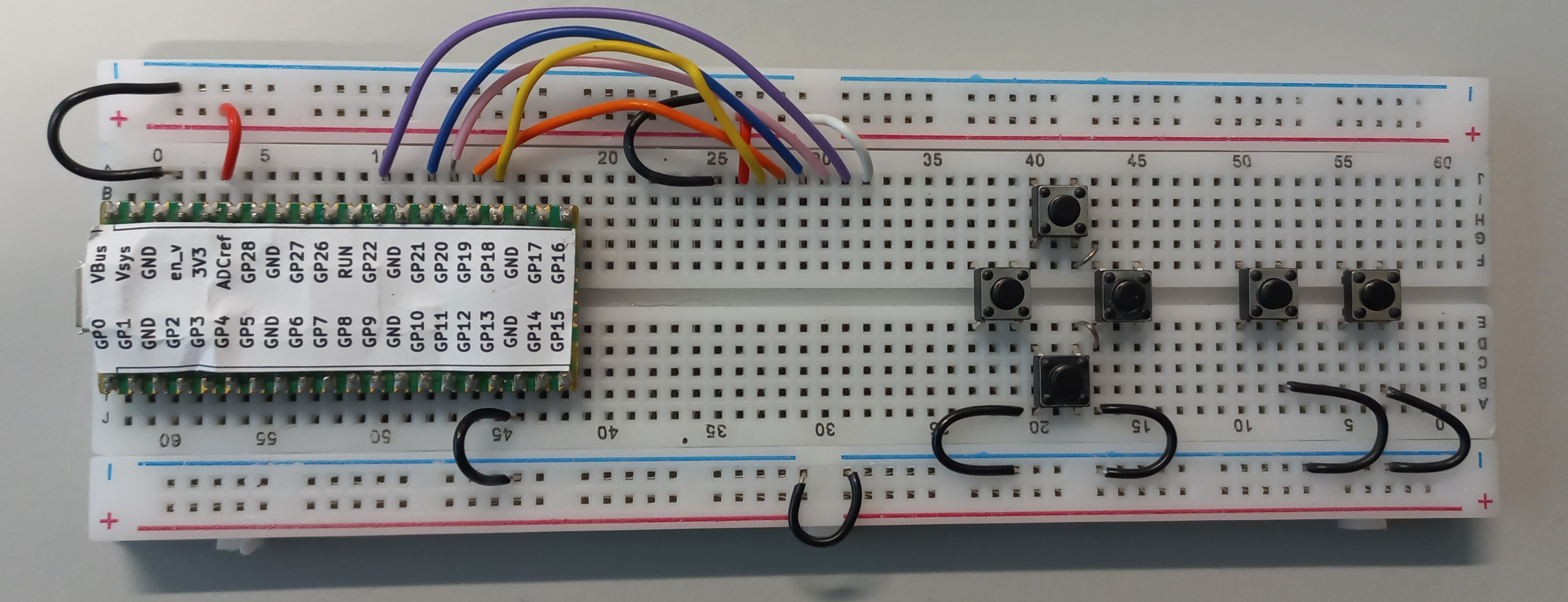
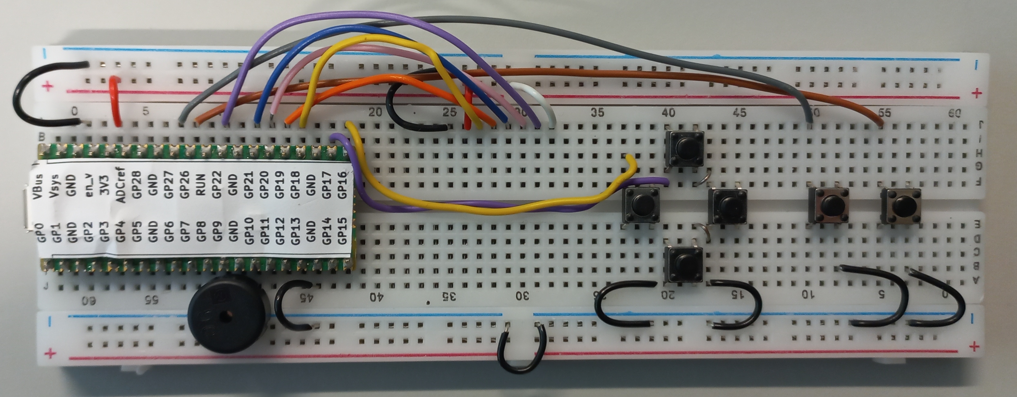
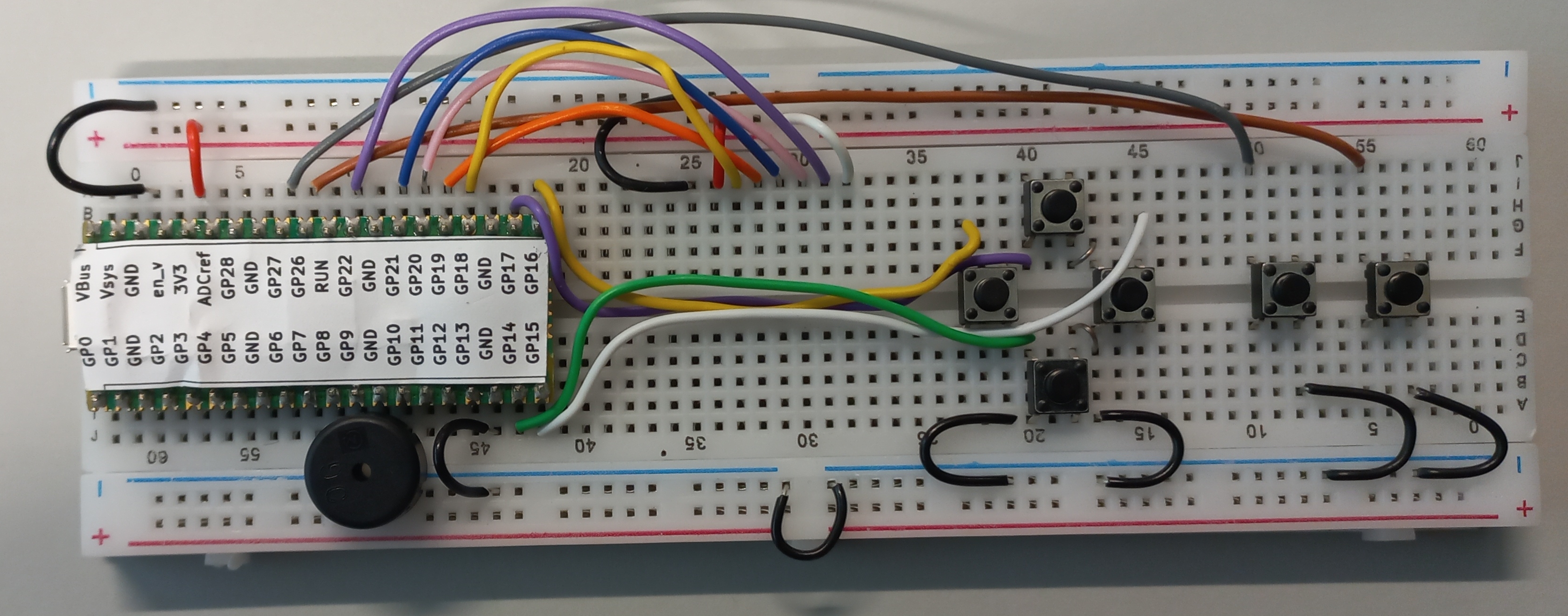
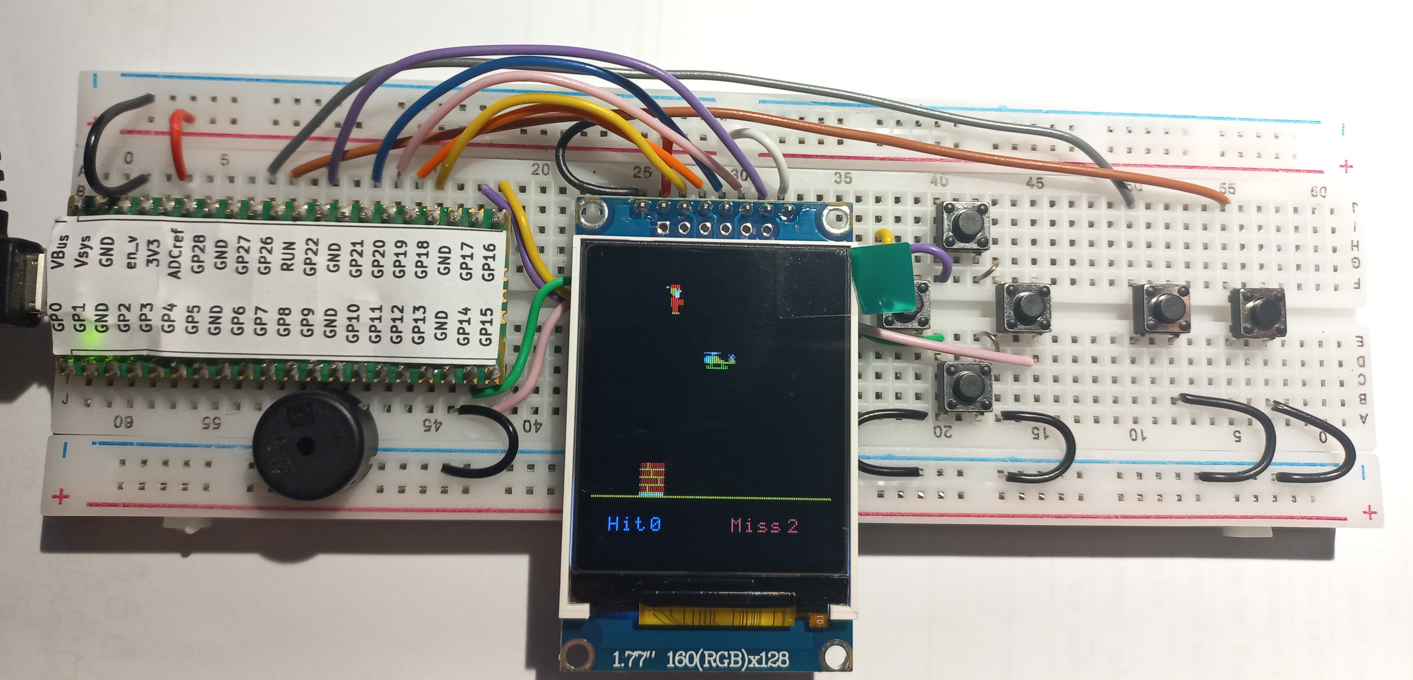
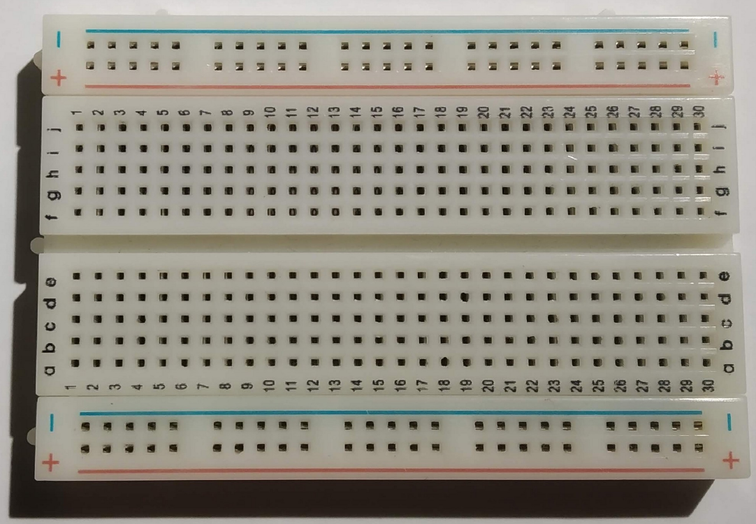
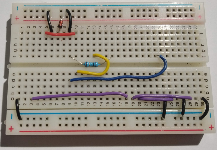
A set of construction images is shown below. Be careful to place the wires and components exactly as shown. The breadboard has rows labelled a to j and columents 1 to 63 which may help when inserting components. If you would like to know more about breadboards this video may help:

Construction image gallery

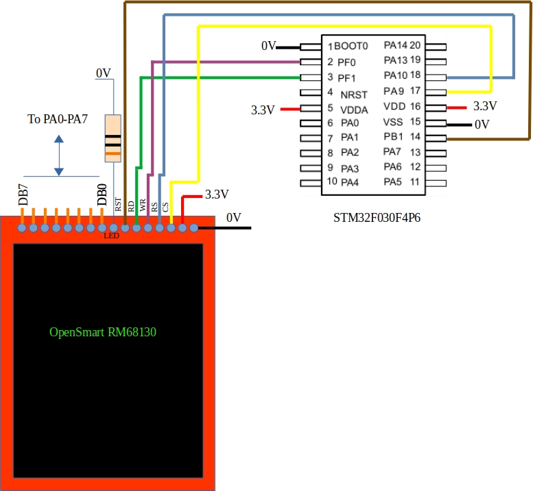
The following three images show the placement of the display wires and grounds on this board

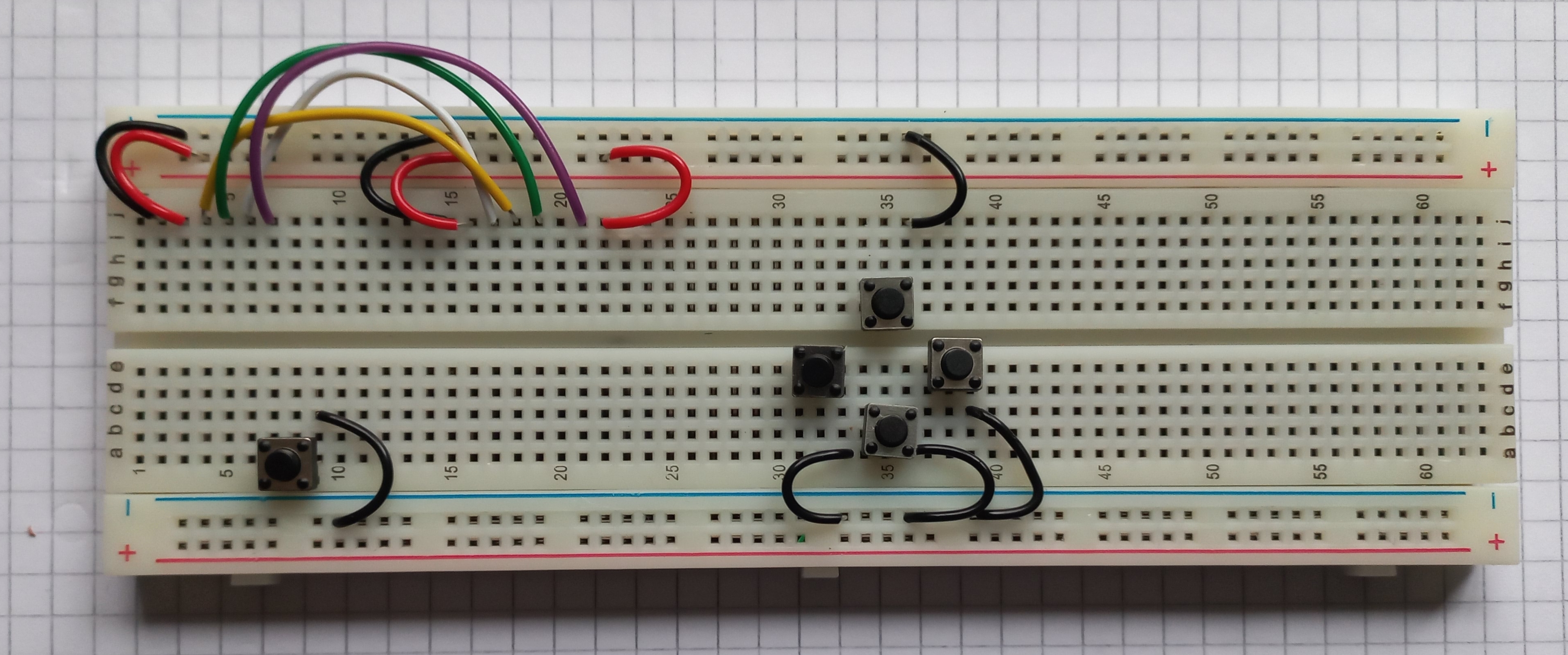
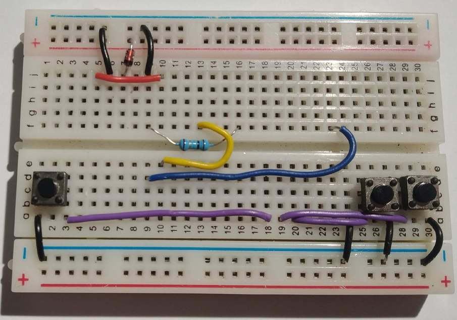
The image below shows the placement of the gamepad wiring. Be sure to run the wires in the slot as shown. The left-most button is equivalent to the A button on a game controller. Its left pin lines up with a pin on the microcontroller development board so no wire is needed for it (apart from ground).

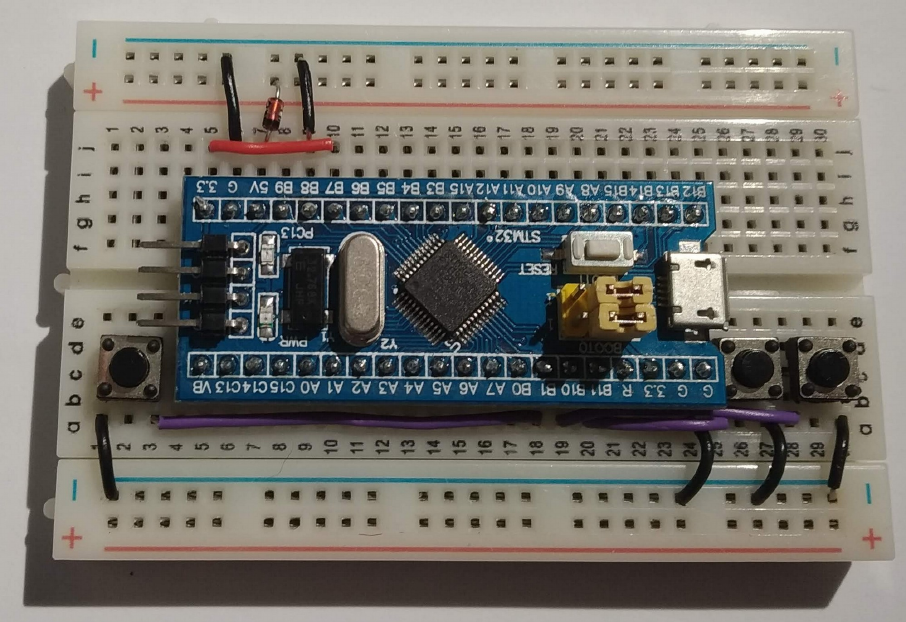
The long black and blue wires are shown below. Be careful to leave space for the microcontroller board when routing the blue wire.

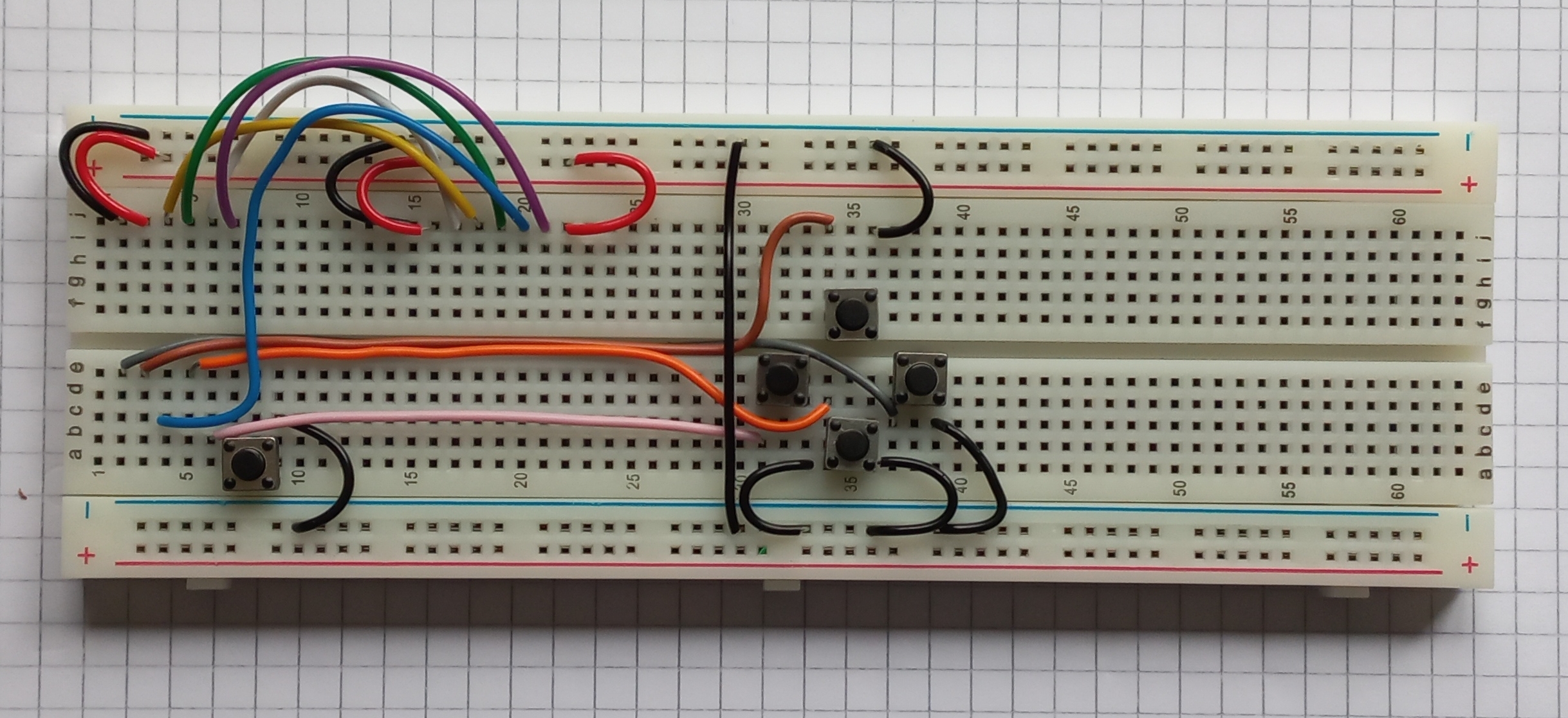
The microcontroller boards is placed as shown. It fits in to the left-most holes of the breadboard.

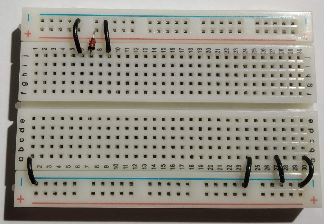
The buzzer placement is shown below. One pin goes into the ground track of the breadboard, the other wire goes to the leftmost column of the breadboard just below the microcontroller board.

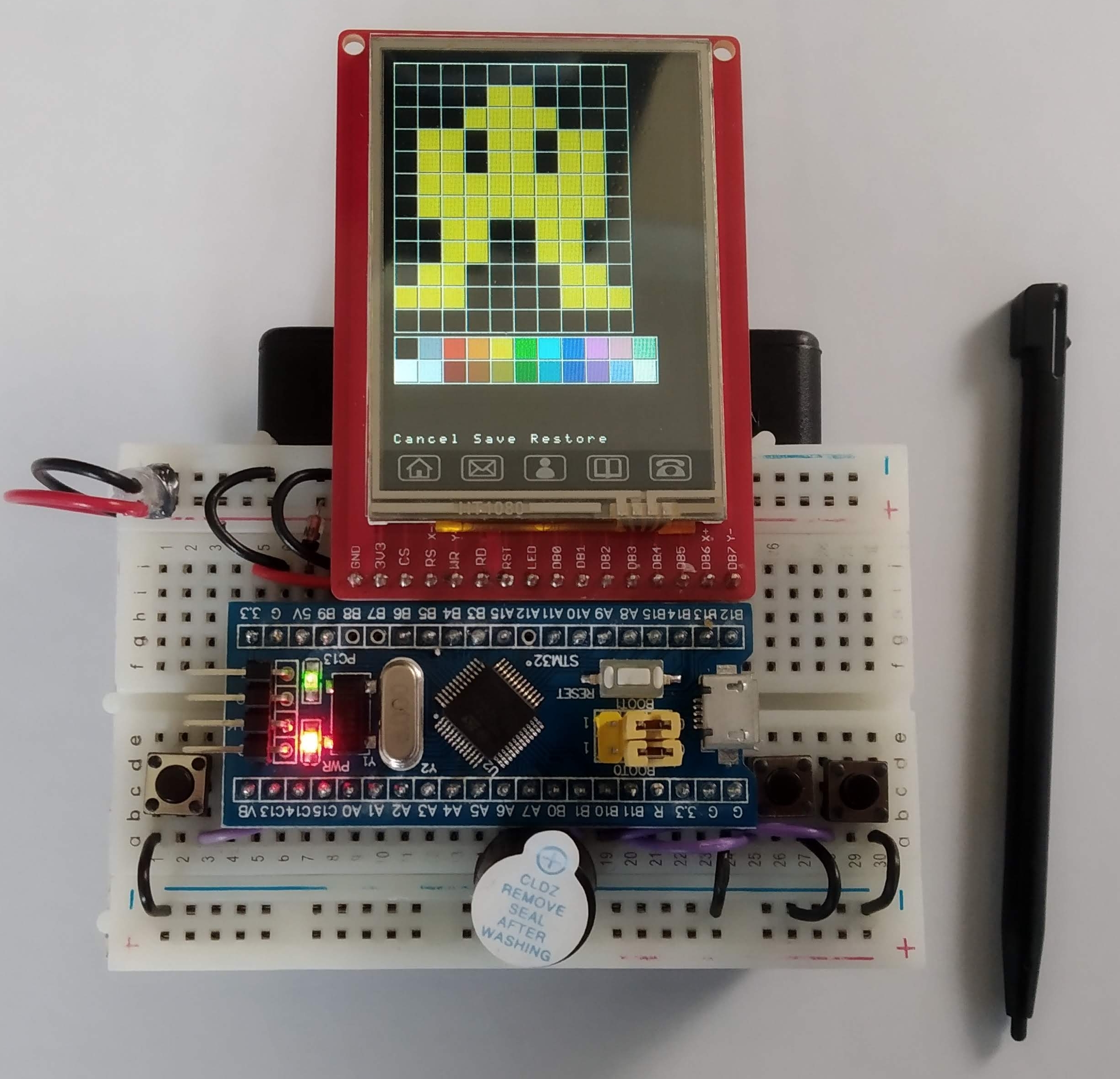
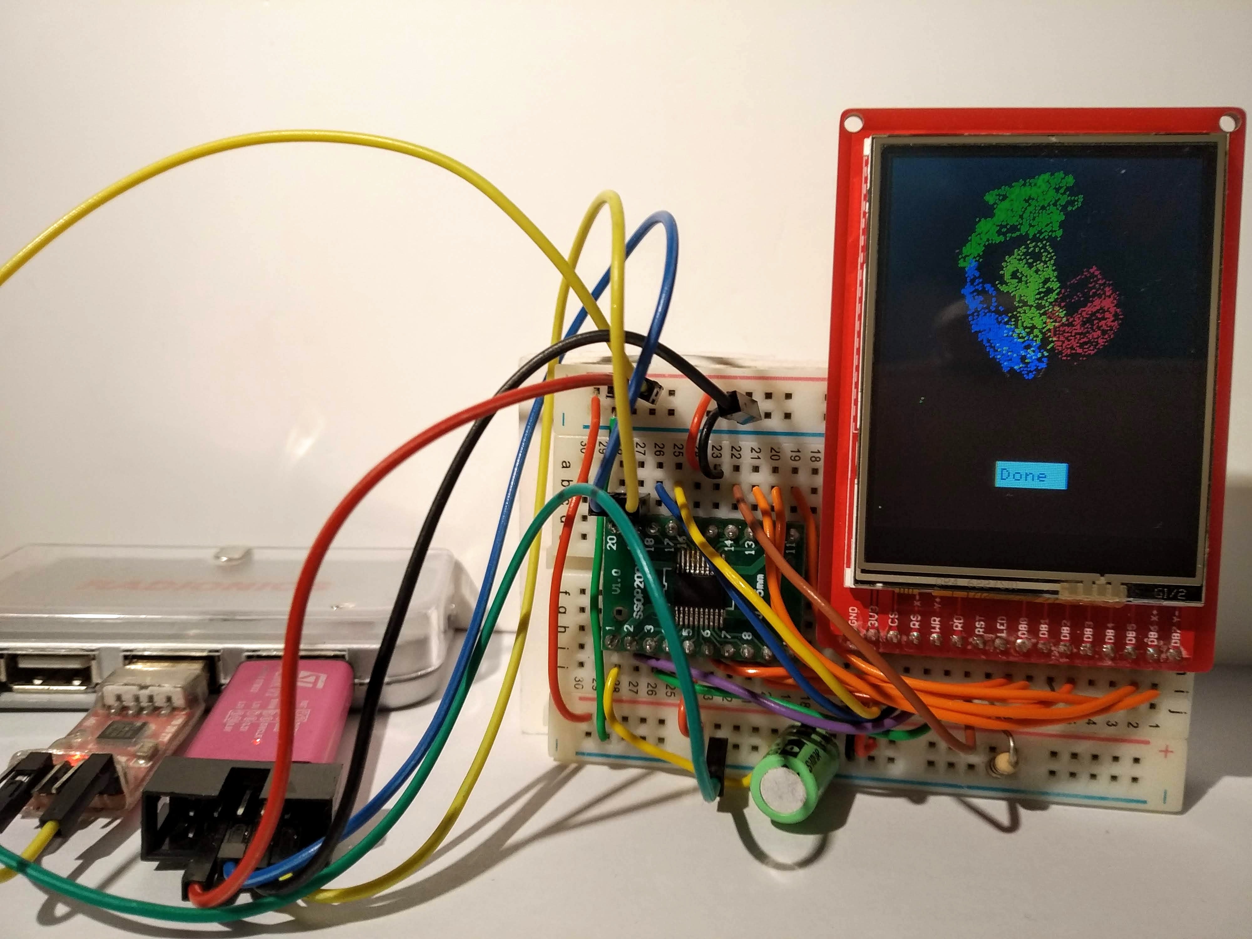
Finally, fit the display as shown below. Be careful to line up the pins with the wires as shown.

Programming

Our game console is programmed in Micropython which is best accessed using the Thonny development environment. There are three ready-made games which will hopefully help your learning of micropython and the hardware on our board. There is also a place for you to create your own game. When the board starts you are presented with a menu which allows you select from these (press A to select). There are lots of micropython and python learning resources on the Internet. The basics of Python can be studied here: https://www.w3schools.com/python/. Micropython tutorials tend to be board specific. A tutorial for our XIAO board can be found here: https://wiki.seeedstudio.com/XIAO-RP2040-with-MicroPython/. Board documentation is available here (check the rpi2040 chapter): https://files.seeedstudio.com/wiki/XIAO/Seeed-Studio-XIAO-Series-SOM-Datasheet.pdf

The code you will use in this exercise includes additionaly libraries to manage our specific hardware. This hardware includes the display, the buzzer, the various buttons and the onboard RGB led. Here is a list of the functions within these libraries.

Functions that control the display
putPixel(x,y,colour): lights up a display pixel with the specified location and colour
drawLine(x0,y0,x1,y1,colour): x0,y0 = start point, x1,y1 = end point
fillRectangle(x1,y1,w,h,colour): x1,y1 = top left corner, w=width, h=height
drawRectangle(x1,y1,w,h,Colour): x1,y1 = top left corner, w=width, h=height
clear(): clear the screen to black
putImage(x,y,w,h,img,horiz,vert): put image at x,y. Width is w, height is h. Image data is in img and h,v specify whether image is inverted in horizontal or vertical axes
setOrientation(h,v): set display orientation (0,0) = default
print(text, x, y, forecolour, backcolour): print text at x,y with foreground and background colours
drawCircle(x0,y0,radius,colour): circle with
fillCircle(x0,y0,radius,colour):
RGBToWord(r,g,b): convert 8 bit red, green and blue values to a 16 bit colour value

Functions that use the gamepad buttons
leftPressed(): returns 1 if the left button was pressed
rightPressed(): returns 1 if the right button was pressed
downPressed(): returns 1 if the down button was pressed
upPressed(): returns 1 if the up button was pressed
aPressed(): returns 1 if the A button was pressed
buttonPressed(): returns a bit patten for the various buttons (0 if nothing pressed)

Functions that manage sound
sound.tune.append() : append a note to the sound array
sound.note(frequency,duration,pause)

Sprite functions
sprite(x,y,w,h,image,display): creates at sprite with the initial position x,y. Bounding rectangle height=h,width=w
show(): show the sprite on screen
hide(): hide the sprite
move(newx, newy): move the sprite (erase at the previous location)
move_no_erase(newx, newy): move the sprite (don’t at the previous location)
setOrientation(horiz, vert): set sprite horizontal and vertical orientation (default 0,0)
isOverlapping(sprite2): do this sprite overlap another?

RGB Led support
set_colour(self,red,green,blue): light up the onboard LED with the particular color

Once you have finished building the board (and playing the games) we will explore how you might write your own game. Starter code for this event is available below:

Breadboard Games 2022 Assembly

Note on board co-ordinates:

There are two sets of co-ordinates shown on the board. We will be using the ones that are the “right way up” i.e. the ones shown on the left side of the image. Some of the images can be a little misleading because of the angle the photos were taken. This is particularly true for the red and black wires at the top left of the image. The red wire connects to 3V3 to any hole just above the red line. The black wire connects GND to any hole just below the blue wire.

Display wiring:

White : Column 32, Row A to any hole just above the red line (keep it left of Column 30)

Purple : Column 31, Row A to GP22

Pink : Column 30, Row A to GP20

Blue : Column 29, Row A to GP21

Orange : Column 28, Row A to GP19

Yellow : Column 27, Row A to GP18

Red : Column 26, Row A to any hole just above the red line (3.3V)

Black : Column 25, Row A to any hole just below the blue line (0V)

Buttons: Place as shown.

Black wires (0V) These are used connect GND (0V) signals together.

Link wires between buttons

Column 42, Row E to Column 43, Row D

Column 42, Row F to Column 43, Row G

Button wiring. Try to get at least some of the button wires into the channel between the top and bottom halves of the breadboard.

Brown : GP26 to Column 55, Row A

Grey : GP27 to Column 50, Row A

Purple : GP17 to Column 14, Row E

Buzzer: GP9 to any hole just below the blue line

Yellow: GP16 to Column 36, Row C

White : GP15 to Column 45, Row C

Green: GP14 to Column 40, Row F

WARNING : ASK FOR ASSISTANCE WITH THIS. DISPLAY ARE FRAGILE!

Fit the display as shown in the row of holes just below the display wires. The rightmost pin of the display should line up with the small white wire.

Breaboard games 2022

Breadboard Games 2022 is approaching. This year we will have 16 students assemble the game console shown above. The console consists of a Raspberry Pi Pico linked to an ST7735, some buttons and a piezo speaker. The schematic is shown below

Two simple games are featured: A version of break out and a simple Santa Clause game. These games are written in Micropython with an emphasis on ease of understanding rather than game play. Nevertheless, the graphics module is reasonably optimized with an inline assembler module that executes very quickly and which is used by API functions as much as possible. Furthermore, the sound module makes use of the second core in the Pico which allows sound to be be played at the same time as the game.

The game sprites are edited in a bitmap editor such as Windows Paint or KolourPaint etc. The sprites are created as 24 bit bitmap (bmp) files. A python script converts these bitmaps to python arrays on the host computer. These arrays are coded as 16 bit RGB (5-6-5) colour values which are compatible with the ST7735. These arrays are then included in a sprite module in the game.

Programs were edited using Thonny which is a nice cross-platform editor that works with a number of operating systems. It can be installed without administrator permissions on Windows and Linux systems.

Code is over here on github.

Breadboard Games 2021

Given the pandemic restrictions this year Breadboard Games will be delivered remotely. Participants will each receive a kit and work with a parent to assemble the gaming console. Remote support will be provided via video.

Instructions

This is a breadboard. It allows us to connect electronic components together by pushing them into the holes. In the centre region all the holes in column 1 are connected together inside the board apart from the gap in the middle. Columns 2 to 30 work similarly. You can see more about breadboards at this location


In the outer, between the blue and red lines, connections run horizontally within the breadboard. We usually use these areas to connect power supplies for our electronic components.

Lets begin by putting the black wires into the board as shown above. The top row of holes next to the blue line will be used to distribute the 0V connections for our circuit (the negative terminal on our battery). The connections are expressed in Row,Column terms as follows:

j6 to 0V (approximately directly above just next to the blue line)
j9 to 0V
a1 to 0V
a24 to 0V
a27 to 0V
a30 to 0V

A diode only allows electricity to flow in one direction. We include one here to protect our game in case somebody connects the battery pack in backwards. The diode has two wires : Cathode and Anode.

We want electrical current to flow into hole j7 so put the cathode in there and the anode just above the red line as shown.

Connect the red wire between j5 and j10.
The other component is a resistor. Resistors control the flow of electrical current. We are using this one to limit the brightness of our display so that the batteries last longer. The resistor connections between f9 and f16. Note the way the resistor sits in the valley between both halves of the breadboard.

The screen in our game is a “touch-screen”, just like a phone. We have to add a couple of wires to support this. The yellow wire goes from e10 to f13. The blue wire goes from d9 to f23

The purple wires are used to connect the buttons to the little computer in our game. They are connected as follows:
a3 to a18
a19 to a28
a20 to a25

The buttons go in next. Each button has two “pins” that are connected together electrically when you push down. The left button we will call simply “Left”, the rightmost button we will call “Right” and the middle buttonw we will call “Fire”. The connections are as follows:
Left: c1 and c3
Fire: c25 and c27
Right : c28 and c30

We are nearly done. The computer board that controls our game needs to go in next. Before you put it in be sure that all of the previous connections are correct. It is difficult to remove the computer boards if you need to correct any errors. Push the board firmly into the breadboard with the pin marked “3.3” (top left) in hole g5.

And now for the screen. Be very careful putting this in. It goes in row i. The rightmost pin of the display goes into hole i24. Push down on the pins only, not the glass. The glass will crack if you push on it.

Our game makes sounds. The buzzer is connected between a17 and 0V (just below the blue line). The longer leg of the buzzer (labelled +) goes in to a17.

The battery pack plugs into the board as shown above. Note the red wire is closest to the red line on the breadboard. The on/off switch should be just behind the display on the right hand side. If you like you can stick the breadboard to the battery pack using the adhesive backing on the breadboard. If you decide to do this be very careful as the adhesive backing is very strong.

All software used in this game is available on my github repository

Breadboard games 2020

With the Covid-19 pandemic ongoing it is not likely there will be any further Breadboard Games events this year. There was a small event in early March in Kevin St. public library with children from Singe Street primary school. On that day the attendees built a board very similar to the one we used in
St. Audoen’s school in 2017.

So what about the rest of the year? Well, a couple of events happened this year that made me think of a particular game: the passing of John Horton Conway and the pandemic so the game is of course “The game of life”. Lots has been written about this game and I will not repeat that here, instead I will focus on how this can be implemented using a low cost microcontroller (MCU), screen and breadboard. There will likely not be “event” based on this game but maybe a reader will be inspired to try it out for themselves.

game_of_life_breadboard

The schematic
game_of_life_schematic

This circuits makes use of components I had lying left over from other breadboard games projects. The MCU is the 30 cent (approx) STM32F030F4P6. This display is a 176×220 TFT board with a parallel interface. The databus runs between PA0-PA7 on the STM32 and DB0-DB7 on the display (it is not shown completely as it would have cluttered the schematic).
The specifications of the MCU are pretty meagre: 16kB of Flash, 4kB of RAM, 48MHz clock speed. All pins have been used to control the display.

The game
Conway’s game of life is all about automata (cells) that live or die depending upon what surrounds them. Cells can die of loneliness (less that 2 neighbours), starvation (more than 3 neighbours) and they can come to life if they are bordered by exactly 3 neighbours. These rules are applied repeatedly to the cells in the landscape. I’ve chosen to do this in two passes. The first pass decides what the state of each cell will be during the next time around based on current state. The second pass switches from the old state to the new state. This of course requires memory (RAM) and this MCU only has 4kB. The display has 176×220 = 38720 pixels. The game allocates one pixel per cell so without some sort of compression there is no way this MCU can store this amount of data. To further add to the storage burden I’ve decided to go with a coloured version of GoL called Quad-Life. Each pixel can be one of 4 colours or black. Where can this be stored?

Stealing memory from the Display
The RM68130 display has enough on-board RAM to store 18bits for each of the 176×220 pixels. All of this does not have to be used for controlling the display however. If the display is switched to 8 colour mode then only 3 of those 18 bits is required per pixel (1 for red, 1 for blue and 1 for green). The remaining 15 bits can be used to hold whatever you like without impacting on what you see on screen. At least that was the theory…. I’ve been using various small displays like this for a while and up until now have had little success reading data back from them. The SPI versions are particularly tricky; some don’t even have read-back functionality. Happily the RM68130 does allow you read back from it’s graphics memory but there’s a catch: the bits you write do not come back to you in the same order. Now I’m willing to accept I may have made a mistake here but I found it VERY confusing reading data back from the display. After many hours I figured out enough to store 1 byte of my choosing alongside each pixel. This means the MCU just got an additional 38720 bytes of RAM – plenty for storing the future states of each cell. By the way there are other displays that should work like this. I’ve tried the ST7775 and the ILI9225 (both parallel interfaces) and they both worked fine

Additional game details

GoL has to start somewhere. You need some way of supplying initial states for the cells (pixels). As you can see above there are no more pins available for user input (PA13 and PA14 are used for debugging). One further feature of the display is that also functions as a resistive touch screen. The user now simply draws the initial state using a stylus (or finger).

The GoL landscape is not meant to run in to a hard border so when a cell goes beyond an edge it “wraps” around to the other side.

Gameplay
The video below shows the game “in action”. It is not particularly fast and manages about 1 update per second. Consider it a slightly interactive desk ornament 🙂

The code
Code is as usual available over here on Github. There has be no attempt to optimize the performance of this code in any way. It is shown in what is hopefully the easiest to understand mode.

The STM32F030 driving an ST7789 display

The ST7789 display used in this example is a 1.3 inch 240×240 colour LCD display. It interfaces to the STM32F030 at the pretty fast speed of 24MHz. The display is connected as follows:
stm32f030_st7789_schematic
My intention with this circuit is to create a low cost conference badge (actually for Dublin Maker 2019). The target bill-of-materials cost is €5 – most of which is attributed to the display.
stm32f030_st7789
Full size image
Connecting the hardware is only part of the story however and a software library is also required. This was based on the Breadboard Games code from last August in Wexford. The main changes that had to be addressed were the new initialization code and the openAperture code. These were based on the Adafruit library code and the manufacturer’s datasheet. This library includes some graphic drawing primitives as well as other functions to support game play (e.g. timing and random number generation). Additional functions will be added as the badge develops.
Code is available on github
A video of the library in operation is available on YouTube.