Given the pandemic restrictions this year Breadboard Games will be delivered remotely. Participants will each receive a kit and work with a parent to assemble the gaming console. Remote support will be provided via video.
Instructions
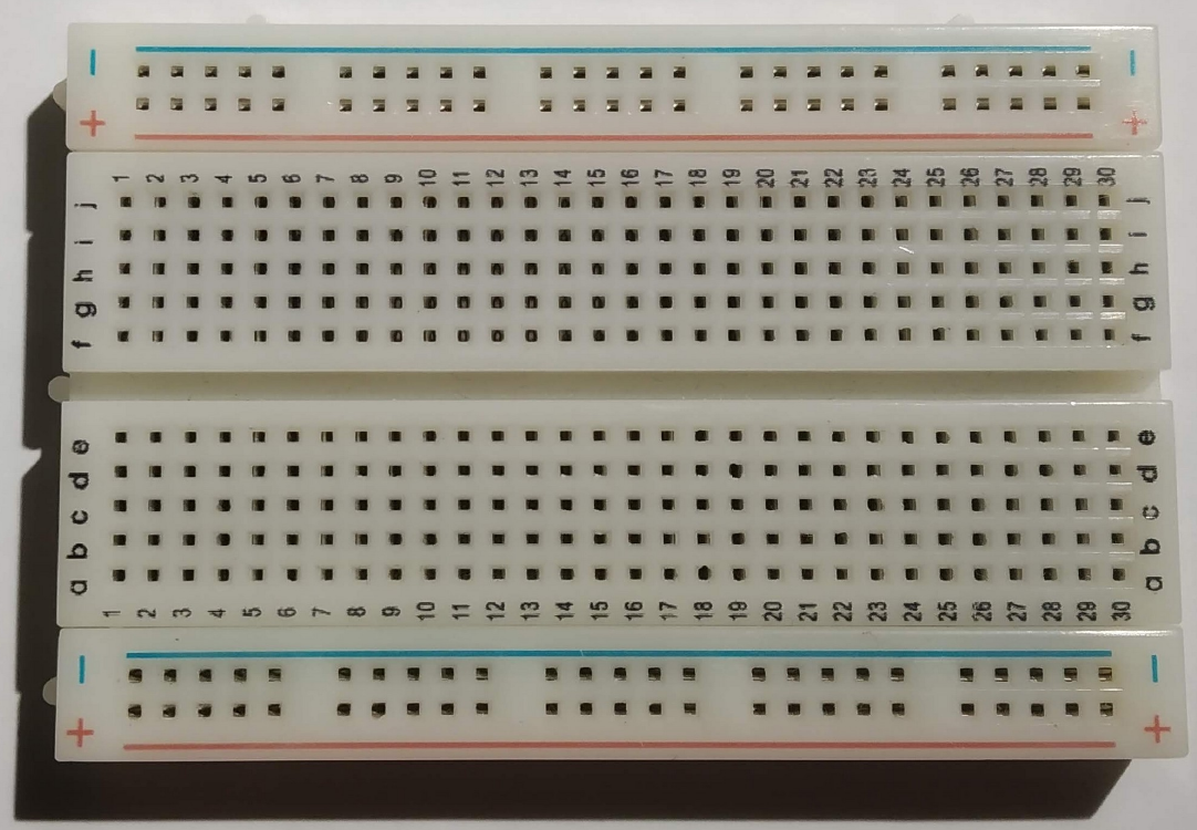
This is a breadboard. It allows us to connect electronic components together by pushing them into the holes. In the centre region all the holes in column 1 are connected together inside the board apart from the gap in the middle. Columns 2 to 30 work similarly. You can see more about breadboards at this location
In the outer, between the blue and red lines, connections run horizontally within the breadboard. We usually use these areas to connect power supplies for our electronic components.
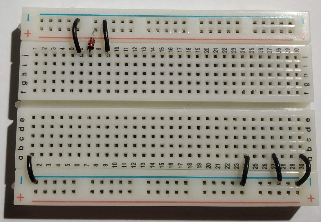
Lets begin by putting the black wires into the board as shown above. The top row of holes next to the blue line will be used to distribute the 0V connections for our circuit (the negative terminal on our battery). The connections are expressed in Row,Column terms as follows:
j6 to 0V (approximately directly above just next to the blue line)
j9 to 0V
a1 to 0V
a24 to 0V
a27 to 0V
a30 to 0V
A diode only allows electricity to flow in one direction. We include one here to protect our game in case somebody connects the battery pack in backwards. The diode has two wires : Cathode and Anode.
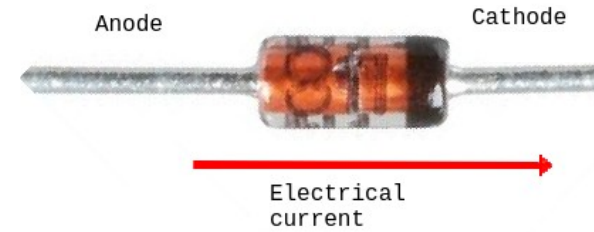
We want electrical current to flow into hole j7 so put the cathode in there and the anode just above the red line as shown.

Connect the red wire between j5 and j10.
The other component is a resistor. Resistors control the flow of electrical current. We are using this one to limit the brightness of our display so that the batteries last longer. The resistor connections between f9 and f16. Note the way the resistor sits in the valley between both halves of the breadboard.

The screen in our game is a “touch-screen”, just like a phone. We have to add a couple of wires to support this. The yellow wire goes from e10 to f13. The blue wire goes from d9 to f23
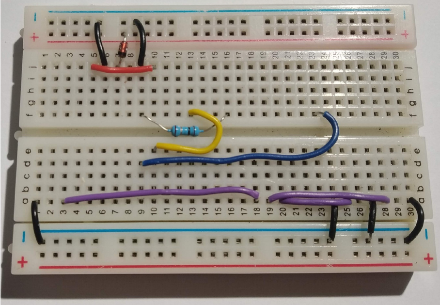
The purple wires are used to connect the buttons to the little computer in our game. They are connected as follows:
a3 to a18
a19 to a28
a20 to a25
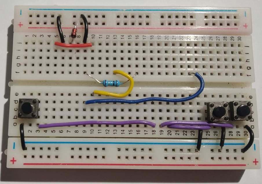
The buttons go in next. Each button has two “pins” that are connected together electrically when you push down. The left button we will call simply “Left”, the rightmost button we will call “Right” and the middle buttonw we will call “Fire”. The connections are as follows:
Left: c1 and c3
Fire: c25 and c27
Right : c28 and c30
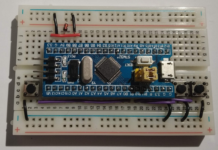
We are nearly done. The computer board that controls our game needs to go in next. Before you put it in be sure that all of the previous connections are correct. It is difficult to remove the computer boards if you need to correct any errors. Push the board firmly into the breadboard with the pin marked “3.3” (top left) in hole g5.
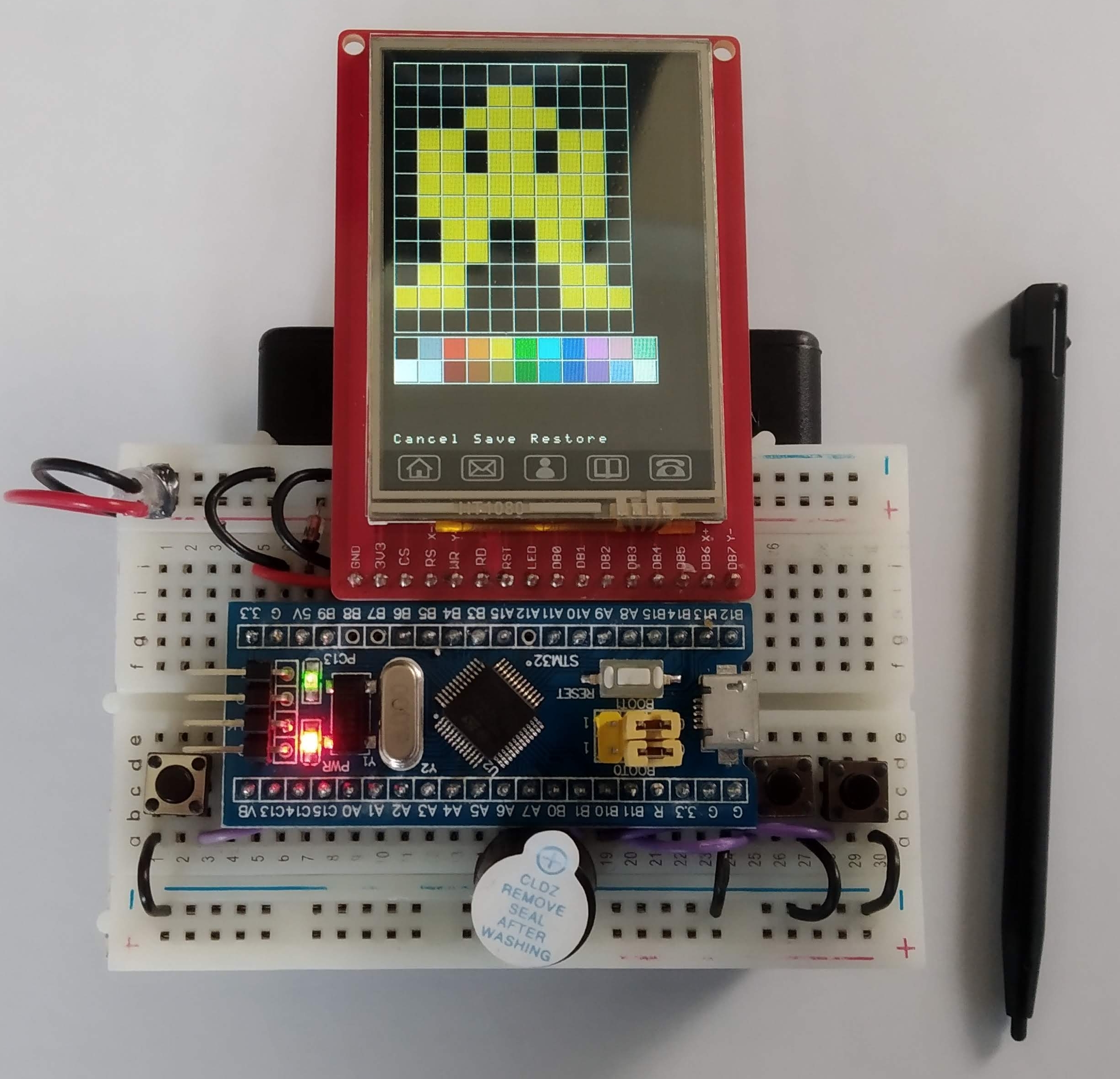
And now for the screen. Be very careful putting this in. It goes in row i. The rightmost pin of the display goes into hole i24. Push down on the pins only, not the glass. The glass will crack if you push on it.
Our game makes sounds. The buzzer is connected between a17 and 0V (just below the blue line). The longer leg of the buzzer (labelled +) goes in to a17.
The battery pack plugs into the board as shown above. Note the red wire is closest to the red line on the breadboard. The on/off switch should be just behind the display on the right hand side. If you like you can stick the breadboard to the battery pack using the adhesive backing on the breadboard. If you decide to do this be very careful as the adhesive backing is very strong.
All software used in this game is available on my github repository
