The STM32F411 “Black Pill” board is a step up in performance from the Blue Pill (STM32F103). It contains a 100MHz ARM Cortex M4F CPU with 512kB Flash and 128kB of RAM. The usual sort of peripherals are also included (ADC, Timers, SPI, I2C etc.).
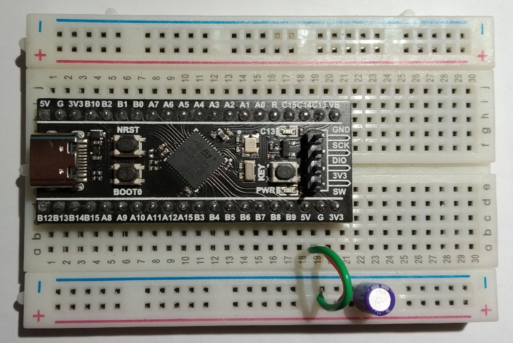
The Black Pill board comes with a set of pads on the underside that can accommodate an SPI flash chip. I was interested in giving this a go so soldered in an ST Micro M25P16 device. This has 2MB of storage that is page programmable (256 Byte pages) and sector erasable (64kB sector size). It also supports a bulk erase function.
There were no great problems getting a driver going except for one thing: When NSS is released (sent high) by the SPI peripheral I found that I had to introduce a short delay in the SPI driver. Without this delay, the interface to the flash chip did not work when one transaction immediately followed another. This may be because the pulse never left the STM32F411, or because of bad wiring, or because the flash chip just needs a moment (the datasheet seems to suggest at lease 100ns of a pause). Anyway, it now works and the image below shows a data read transaction captured using pulseview (Thanks pulseview authors! 🙂 ).
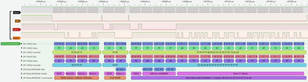
You can just make out the narrow NSS pulses (approx 400ns) that were necessary for the system to work. This image was captured with the SPI bus running at a reduced speed to allow for the limited bandwidth of my logic analyzer.
What could this be used for? Well, a data logger perhaps, or a store for various image assets for a screen or maybe even some sounds. If you use this be mindful of the write cycle limitation of these devices and especially don’t put a write in a fast loop.
Code for this and other examples can be found over on github : https://github.com/fduignan/stm32f411
