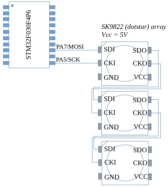
The SK9822 LED (also known as the “dotstar” LED) is a smart RGB LED similar to the WS2812B. It has some advantages however: It is controlled using a standard SPI interface which means it does not rely on the sort of critical timing the WS2812 needed. It also allows you separately control the brightness and the colour mix of the internal LED’s. The LED’s can be strung together; the data and clock output from one feeding the next. The LED’s require use two pins of the host microcontroller: MOSI and SCK as shown in the figure above. Power should be supplied from a separate source to the microcontroller. The SK9822’s are 5V devices but seem to accept 3V logic signals on their control inputs.
The LED’s I got came in the 50/50 surface mount format which makes them a little difficult to use with a breadboard. A TSSOP-20 adapter came in very handy however and I was able to mount 3 on the same board as shown below.

The LED’s are controlled using a data frame that begins with a sequence of the following form
0x00 0x00 0x00 0x00 ii bb gg rr 0xff 0xff 0xff 0xff
The leading 4 zeros are a start of data frame delimiter.
These are followed by a 1 byte intensity or brightness value which ranges from
0 to 31. The most significant 3 bits of the brightness field must be 1
Values in the range 0 to 255 follow for blue green and red
Finally an end of frame consisting of 4 bytes of 0xff is sent.
The test program below outputs signals that cycle 3 LED’s through a range of colours
The program was developed using an STM32F030F4P6 breakout board and ST-Link V2
SWD interface.
Code is available for download from here on github
