The STM32F334 MCU has an ARM Cortex M4F core along with ADC’s, DAC’s and motor control timers – all of which are useful to me for DSP and motor control. My final intention is to design a couple of PCB’s around this chip so rather than buy a ready made board like the STM32F334 Discovery I decided to work directly with the bare chip.
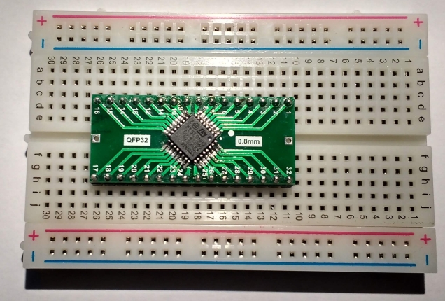
First task is to mount the chip on a breakout board so that I can use it with a breadboard.
Full size image
Some tips when doing this:
Have a good soldering iron that does not get too hot (I have an Antek 25W iron)
Have lots of liquid flux available and apply liberally
Have solder wick to hand to sort out the (inevitable for me) solder bridges
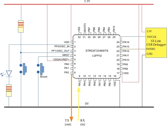
The circuit was wired as shown in the diagram above and is shown here:

I used an ST-Link clone from Aliexpress which costs 2 or 3 Euro.
In the past I have manually written header files for the various internal peripherals. ST Microelectronics provide a System Volume Description file which can be used with SVDConv to create a header file. This header file relies on other components from the ARM CMSIS libraries spread across various folders. I don’t like this so I added various dummy files (some with zero content) to the same directory as the generated header file. This allows me confine all header files to one directory and is completely standalone.
Having done all of this various examples were written and the code repository is over at github. This will grow over time but for now there are examples of blinky, systick interrupts, UART i/o and the ADC.
Month: January 2019
Using the TLS2561 to wake the STM32L031 from sleep

In some ways this example is a bit illogical. The TLS2561 consumes a few hundred micro amps while operating so using it to wake the STM32L031 from sleep doesn’t make a lot of sense. This example may be relevant to those who want to use an external I/O pin to wake the an STM32L031 generally or maybe as part of a larger circuit.
The TLS2561 can generate an interrupt signal when the light received on Channel 0 goes outside a user specified certain range. In this example, the range was arbitrarily set to go from 0 0x100. If the received light is equal to or greater than 0x100 then the interrupt signal is driven low which wakes the MCU. If the light is less than or equal to 0 an interrupt is also generated. This isn’t exactly what I wanted (I only wanted an interrupt if the light was bright) so if the circuit is plunged into complete darkness an interrupt will also be generated. This unintended waking could be dealt with by checking the value on Channel 0 and, if zero, going back to sleep again.
Code is available as usual over on github.
