UPDATE!
3rd of March 2018
The code in this example has been updated. See here:
https://wordpress.com/post/ioprog.com/1628
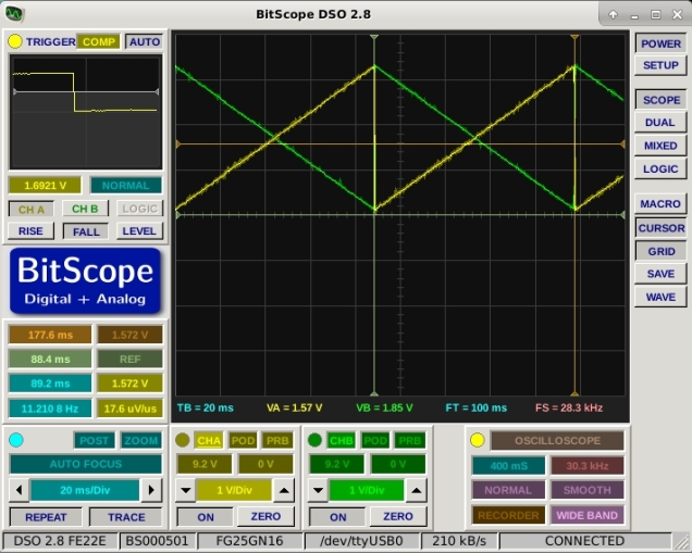
This example combines two previous posts regarding the TLV5618 DAC and timer interrupts with the MSP432 Launchpad. The project reads the A0 analog input at 22050Hz (half CD quality) and outputs the reading via the TLV5618 Channel A DAC. Higher sample rates are possible but an error creeps in due to overhead handling the DAC. This example also corrects an error in the previous post about timer interrupts which assumed that the timer base frequency was 16MHz – it seems to be 12MHz in fact. The output for a 1kHz sinewave is shown below.

The code is here.
// This program does an analog pass through between Analog input A0 (P5.5)
// on the MSP432 Launchpad and a TLV5618 SPI DAC.
// The green LED is used to indicate that the program is still alive :o)
// Further details at ioprog.com

#include
#include
#include
#include
#define SS_PIN 17
void setup()
{
  // put your setup code here, to run once:
  pinMode(SS_PIN,OUTPUT);
  pinMode(15,OUTPUT); // MOSI
  pinMode(7,OUTPUT); // SCK
  SPI.setModule(EUSCI_B0_MODULE); // Select correct SPI interface
  SPI.setDataMode(SPI_MODE2);
  SPI.setBitOrder(MSBFIRST);
  SPI.setClockDivider(SPI_CLOCK_DIV2); // DIV2 = 8MHz, DIV4 = 4MHz, DIV8 = 2MHz etc. (from measurement)
  UCB0CTLW0 &= ~(BIT0); // Take SPI out of reset
  pinMode(BLUE_LED,OUTPUT);
  pinMode(GREEN_LED, OUTPUT);
  setupTimer(1000000/22050); // Set sample frequency to 22050 : Period=(1000000 microseconds / desired sample rate)
  analogReadResolution(12); // set the ADC resolution to 12 bits (match the DAC)
}


void loop()
{ // Nothing happens here: it is all interrupt driven - see OnTimer for main processing code.
}
void OnTimer()
{

  writeDACA(analogRead(A0)); // write out what is coming in on A0
  // The following simply flashes the green LED to show the program is still running
  static int Count = 0;
  static int state = 0;
  Count++;
  if (Count > 22050)
  {
    Count = 0;
    digitalWrite(GREEN_LED,state);
    if (state)
      state = 0;
    else
      state = 1;
  }

}

void writeDACA(int Value)
{
  Value=Value & 0xfff;
  Value = Value | 0xc000; // Write DAC A
  digitalWrite(SS_PIN,LOW); // Drive CS low
  UCB0TXBUF=( (Value >> 8) & 0xff); // write high byte
  while(UCB0STATW & BIT0); // wait while SPI busy
  UCB0TXBUF=  ( Value  & 0xff); // write low byte
  while(UCB0STATW & BIT0); // wait while SPI busy
  digitalWrite(SS_PIN,HIGH); // Drive CS High
}
void writeDACB(int Value)
{
  Value=Value & 0xfff;
  Value = Value | 0x4000; // Write DAC B value to buffer and update
  digitalWrite(SS_PIN,LOW); // Drive CS low
  UCB0TXBUF=( (Value >> 8) & 0xff); // write high byte
  while(UCB0STATW & BIT0); // wait while SPI busy
  UCB0TXBUF=  ( Value  & 0xff); // write low byte
  while(UCB0STATW & BIT0); // wait while SPI busy
  digitalWrite(SS_PIN,HIGH); // Drive CS High
}
void writeDACs(int AValue, int BValue)
{

  // Write both DACs and update outputs simultaneously.
  BValue=BValue & 0xfff;
  BValue = BValue | 0x5000; // Write DAC B value to buffer
  digitalWrite(SS_PIN,LOW); // Drive CS low
  UCB0TXBUF=( (BValue >> 8) & 0xff); // write high byte
  while(UCB0STATW & BIT0); // wait while SPI busy
  UCB0TXBUF=  ( BValue  & 0xff); // write low byte
  while(UCB0STATW & BIT0); // wait while SPI busy
  digitalWrite(SS_PIN,HIGH); // Drive CS High
  digitalWrite(SS_PIN,LOW); // Drive CS low
  AValue=AValue & 0xfff;
  AValue = AValue | 0xc000; // Write DAC A and update B
  digitalWrite(SS_PIN,LOW); // Drive CS low
  UCB0TXBUF=( (AValue >> 8) & 0xff); // write high byte
  while(UCB0STATW & BIT0); // wait while SPI busy
  UCB0TXBUF=  ( AValue  & 0xff); // write low byte
  while(UCB0STATW & BIT0); // wait while SPI busy
  digitalWrite(SS_PIN,HIGH); // Drive CS High

}
volatile uint32_t millisecondCounter=0;
int count = 0;
volatile int state = HIGH;
volatile int flag = HIGH;
void setupTimer(unsigned Period)
{

  // Configuration word
  // Bits 15-10: Unused
  // Bits 9-8: Clock source select: set to SMCLK (12MHz)
  // Bits 7-6: Input divider: set to 4
  // Bits 5-4: Mode control: Count up to TACCRO and reset
  // Bit 3: Unused
  // Bits 2: TACLR : set to initially clear timer system
  // Bit 1: Enable interrupts from TA0
  // Bit 0: Interrupt (pending) flag : set to zero (initially)
  TA3CTL=0b0000001010010110;
  TA3CCR0=Period*3; // Set TACCR0 = Period (3MHz clock)
  TA3CCTL0=BIT4; // Enable interrupts when TAR = TACCR0
// The following places the address of our interrupt service routine in the RAM based interrupt vector table
// The vector number is 14 + 16  = 30 which is represented by the symbol INT_TA3_0
  Interrupt_registerInterrupt(INT_TA3_0,timerA3ISR);

  // according to the datasheet Table 6-12 timer A3 is on ISR 14
  NVIC_ISER0 = (1<<14); // enable this interrupt in the NVIC

}

void timerA3ISR(void)
{
  TA3CTL &= ~1;         // Acknowledge the interrupt
  TA3CCTL0 &= ~1;       // Acknowledge the interrupt
  NVIC_ICPR0 = (1<<14); // clear interrupt pending flag in NVIC
  millisecondCounter++;
  OnTimer();
}