STLink V2 clone debugger: $1.79
MCU breakout board : $1.68
Total : $3.47
Delivery time : 2 weeks
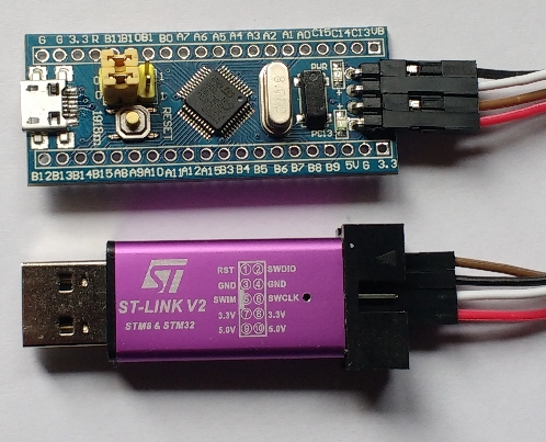
This development kit is based around the stm32f103C8T6MCU. This is a 72MHz Cortex M3 device with 64kB of flash memory and 20kB of RAM. The debugger is an ST-Link V2 clone which can be used to debug STM32 and STM8 devices. I used this with OpenOCD and needed to edit/creaqte the configuration files stm32f103_aliexpress.cfg and stm32f1x_64k.cfg (see below for contents of these files). Note: the register that tells OpenOCD the size of system flash incorrectly indicates 128kB so a value of 64kB is forced in the configuration file. The first test program was blinky of course but this time I decided NOT to write the device header file myself but instead make use of ST Microelectronics
System View Description file (SVD file) for this device. This can be downloaded from here: http://www.st.com/resource/en/svd/stm32f1_svd.zip. Contained in the zip file is STM32F103.svd : an XML description of the peripheral registers within the STM32F103. A separate utility called SVDConv.exe was used to convert this “svd” file to a header file suitable for use with GCC. The SVDConv utility was found in Keil’s ARM MDK (http://www2.keil.com/mdk5/). I’m working in Linux so the conversion command was:
wine ./SVDConv.exe STM32F103.svd --generate=header
This produced the header file STM32F103.h. The header uses structure definitions and pointers to structures to access peripherals and the registers within them. It also has a couple of dependencies include/core_cm3.h and include/system_ARMCM3.h. I started down the road of finding these only to realise that these too had further dependencies. Furthermore, they served to hide a lot of the startup code, interrupt vectors and so on that I like to keep an eye on. So, there are two choices: either remove the #include statements for the dependencies or create empty files with those names. I did the latter as it left the STM32F103.h file unchanged. An additional header file of my own (cortexm3.h) is needed to fix up a couple of missing symbols which are defined as shown below (other symbols are also defined):
#define __IO volatile
#define __IM volatile
#define __OM volatile
These symbols refer to Input/Output datatypes which should probably always be volatile – in short it works.
As an experiment, I tried using STM32Cube to generate code for a simple blinky project. First of all, I should say that it worked (more or less – I had to manually edit the output Makefile to point to the directory where arm-none-eabi-gcc was installed). This is probably a great tool for a company that is producing a range of products across different members of the ARM-Cortex family. From a teaching and learning perspective though the generated code is of limited use. It is littered with conditional compiles, helper functions that hide important details, and requires you place your code between various sets of comments. The generated code is also MUCH larger than the version below. In short it obscures the lower levels of the microcontroller that I’m interested in teaching. The approach I’ve taken here is to use the device’s SVD file for the peripherals and my own, simpler, device specific Cortex M3 cpu core file. I also used my own simplified initialization code to show exactly what goes on after reset.
Blinky
/* User LED is on PC13 */
#include <stdint.h>
#include "../include/cortexm3.h"
#include "../include/STM32F103.h"
void delay(uint32_t dly)
{
    while(dly--);
}
int main()
{
    // Turn on GPIO C
    RCC->APB2ENR |= BIT4;
    // Configure PC13 as an output
    GPIOC->CRH |= BIT20;
    GPIOC->CRH &= ~(BIT23 | BIT22 | BIT21);
    while(1)
    {
        GPIOC->ODR |= BIT13;
        delay(1000000);
        GPIOC->ODR &= ~BIT13;
        delay(1000000);
    }
}
This is built with a script file (or batch file) that executes the following commands:
arm-none-eabi-gcc -static -mthumb -g -mcpu=cortex-m3 *.c -T linker_script.ld -o main.elf -nostartfiles
arm-none-eabi-objcopy -g -O binary main.elf main.bin
The second line of this is not necessary strictly speaking. I use the same script for mbed boards and the “bin” output format is useful there.
Running and debugging
I tried to write out all of the steps in this but decided that a video would be much better. Its over here:
Further examples
A number of other examples are to be found over here https://github.com/fduignan/stm32f103c8t6. These include Systick (at default 8MHz) speed, Systick at 72MHz and UART input/output.
Appendix: OpenOCD configuration files
stm32f103_aliexpress.cfg:
# FILE: stm32f103_aliexpress.cfg
# stm32f103 board and ST-Link v2 from Aliexpress
source [find interface/stlink-v2.cfg]
transport select hla_swd
set WORKAREASIZE 0x2000
source stm32f1x_64k.cfg
reset_config none
stm32f1x_64k.cfg
# FILE: stm32f1x_64k.cfg
# MODIFIED: script for stm32f1x family : forced Flash size to 64kB

#
# stm32 devices support both JTAG and SWD transports.
#
source [find target/swj-dp.tcl]
source [find mem_helper.tcl]

if { [info exists CHIPNAME] } {
   set _CHIPNAME $CHIPNAME
} else {
   set _CHIPNAME stm32f1x
}

set _ENDIAN little

# Work-area is a space in RAM used for flash programming
# By default use 4kB (as found on some STM32F100s)
if { [info exists WORKAREASIZE] } {
   set _WORKAREASIZE $WORKAREASIZE
} else {
   set _WORKAREASIZE 0x1000
}

#jtag scan chain
if { [info exists CPUTAPID] } {
   set _CPUTAPID $CPUTAPID
} else {+
   if { [using_jtag] } {
      # See STM Document RM0008 Section 26.6.3
      set _CPUTAPID 0x3ba00477
   } {
      # this is the SW-DP tap id not the jtag tap id
      set _CPUTAPID 0x1ba01477
   }
}

swj_newdap $_CHIPNAME cpu -irlen 4 -ircapture 0x1 -irmask 0xf -expected-id $_CPUTAPID

if { [info exists BSTAPID] } {
   # FIXME this never gets used to override defaults...
   set _BSTAPID $BSTAPID
} else {
  # See STM Document RM0008
  # Section 29.6.2
  # Low density devices, Rev A
  set _BSTAPID1 0x06412041
  # Medium density devices, Rev A
  set _BSTAPID2 0x06410041
  # Medium density devices, Rev B and Rev Z
  set _BSTAPID3 0x16410041
  set _BSTAPID4 0x06420041
  # High density devices, Rev A
  set _BSTAPID5 0x06414041
  # Connectivity line devices, Rev A and Rev Z
  set _BSTAPID6 0x06418041
  # XL line devices, Rev A
  set _BSTAPID7 0x06430041
  # VL line devices, Rev A and Z In medium-density and high-density value line devices
  set _BSTAPID8 0x06420041
  # VL line devices, Rev A
  set _BSTAPID9 0x06428041
}

if {[using_jtag]} {
 swj_newdap $_CHIPNAME bs -irlen 5 -expected-id $_BSTAPID1 \
	-expected-id $_BSTAPID2 -expected-id $_BSTAPID3 \
	-expected-id $_BSTAPID4 -expected-id $_BSTAPID5 \
	-expected-id $_BSTAPID6 -expected-id $_BSTAPID7 \
	-expected-id $_BSTAPID8 -expected-id $_BSTAPID9
}

set _TARGETNAME $_CHIPNAME.cpu
target create $_TARGETNAME cortex_m -endian $_ENDIAN -chain-position $_TARGETNAME

$_TARGETNAME configure -work-area-phys 0x20000000 -work-area-size $_WORKAREASIZE -work-area-backup 0

# flash size will NOT be probed: Force to 64k (error in chip config register)
set _FLASHNAME $_CHIPNAME.flash
flash bank $_FLASHNAME stm32f1x 0x08000000 0x10000 0 0 $_TARGETNAME

# JTAG speed should be <= F_CPU/6. F_CPU after reset is 8MHz, so use F_JTAG = 1MHz
adapter_khz 1000

adapter_nsrst_delay 100
if {[using_jtag]} {
 jtag_ntrst_delay 100
}

reset_config srst_nogate

if {![using_hla]} {
    # if srst is not fitted use SYSRESETREQ to
    # perform a soft reset
    cortex_m reset_config sysresetreq
}

$_TARGETNAME configure -event examine-end {
	# DBGMCU_CR |= DBG_WWDG_STOP | DBG_IWDG_STOP |
	#              DBG_STANDBY | DBG_STOP | DBG_SLEEP
	mmw 0xE0042004 0x00000307 0
}

$_TARGETNAME configure -event trace-config {
	# Set TRACE_IOEN; TRACE_MODE is set to async; when using sync
	# change this value accordingly to configure trace pins
	# assignment
	mmw 0xE0042004 0x00000020 0
}