The image above shows a Microbit V1 connected to an ST7789 1.14′ display via a Kitronik breakout board. The SPI interface on the Microbit (NRF51822) is a little slow at 4MHz but it is ok for simple outputs as shown above. Code was developed using VSCode, PlatformIO the mbed framework. The full list of connections can be found in the file display.cpp which is available on the github repo over here
The NRF52832 is a Bluetooth microcontroller from Nordic Semiconductor. Boards and modules based on it are available from a number of different suppliers. I got a few on Aliexpress that bear the Ebyte logo. These were pre-programmed (and locked) with a software image from Ebyte. As I planned writing my own code I had to first unlock the device. Normally I work with an STLink debugger (clone) but this is apparently not able to unlock the NRF52832. Fortunately I had previously bought a J-Link Edu probe and this able to unlock the module.
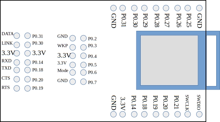
The next hurdle was to figure out which pin is which as the board labels are specific to some other application. With a bit of fishing around datasheets and poking with a multimeter I came up with this:
The pin numbers could now be related to port numbers in the NRF52832.
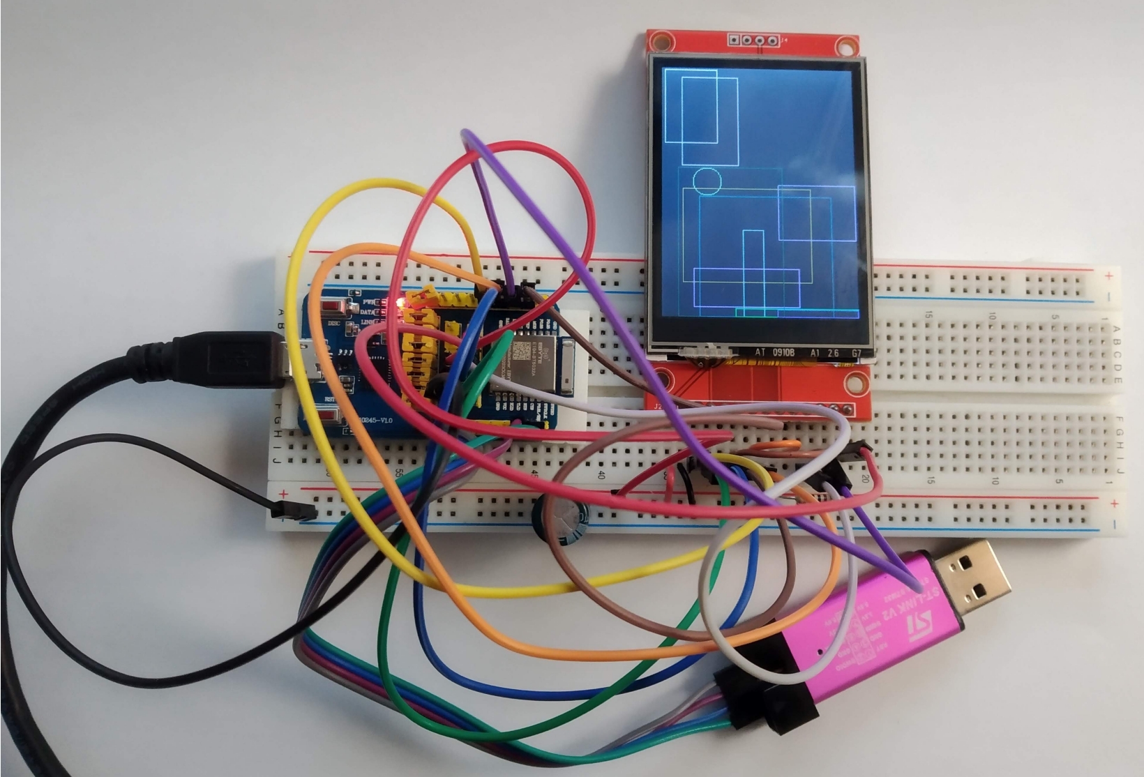
Next the device had to be connected up to the ILI9341 display module. This too was bought on AliExpress. It is an SPI device that includes a touch screen controller. The wiring to the NRF52832 module is as follows:
ili9341
NRF52832
Remarks
T_IRQ
P0_4
0 if screen is touched
T_DO
P0_26
MISO
T_DIN
P0_25
MOSI
T_CS
P0_5
Chip select for touch interface (active low)
T_CLK
P0_27
SPI clock
SDO (MISO)
N/C
LED
Via 10 ohm resistor to ground
SCK
P0_27
SPI clock
SDI (MOSI)
P0_25
MOSI
D/C
P0_6
Switches between data and command mode (0=Command mode)
RESET
P0_7
Clear to 0 to reset the display
CS
P0_28
Chip select for display (active low)
GND
0V
VCC
3.3V
MBed and Visual Studio Code / PlatformIO were used to write code for the device. Initially Mbed was used but it can be slow at certain times of the day so I switched to VSC/PlatformIO for local development. This was a little fiddly to set up but it worked out very well in the end. MBed OS was used as a basis for the code and a working demo is available over here.
Mbed does not have a board support library for this specific board however the DELTA DFBM-NQ620 board uses the same NRF52832 module and works fine.
There were a couple issues along the way:
The NRF52832 has a maximum SPI speed of 8MHz which is a little slow for a display like this.
The Touch screen controller does not work well with the 8MHz SPI clock rate so this is switched down to 2MHz temporarily when reading the touch interface.
The CJMCU-8223 is a small breakout board featuring an NRF51822 and an LIS3DH accelerometer. It is shown above attached to an SSD1306 Oled display. Programs are loaded on to it using an ST-Link debugger clone.
There are many different ways to program this chip but I decided to develop code for it using the online compiler at mbed.org. This environment allows you write and compile code within your browser. Compiled programs are dropped in to your downloads directory in the form of “hex” files. These downloads can then be written to your target MCU using your preferred debugger. The advantage of this approach is that you don’t have to set up a toolchain on your PC and, you can avail of lots of ready made libraries and example code.
This particular example provides two Gatt services over BLE. An LEDService allows a connected bluetooth device to control the blue LED on the breadboard. An accelerometer service allows the connected device read the accelerometer values (scaled up by a factor of 1000 to avoid floating point printing). The code for this example can be found via this link over at mbed.org.
When you compile this code, the hex file delivered to your PC needs to be uploaded to the NRF51822. This is done as follows:
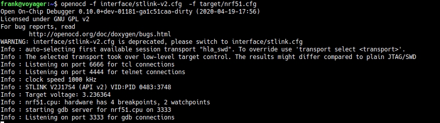
In one command window (terminal) start openocd as shown here:
Leaving that window running, open a new one and run telnet entering the commands shown below.
Once you have done this, type reset into the telnet session and the board should start running.
You can interact with the board using BLE Scanner on your phone or maybe work with node.js or python to develop a PC based application.
If you need to do some debugging, it is possible to export the program from the mbed environment into a format that is compatible with a number of toolchains (including gcc/gdb). I have tried this and it works pretty well although you may need to disable interrupts on the MCU while doing this as the debugger can get confused if there is bluetooth activity during the debug session.
This example uses a 4th order Butterworth low pass filter that was designed in GNU Octave. The sampling rate was set to 200kHz and the cut-off frequency was set to 20kHz. The filter output at 20kHz is shown below and, as expected, shows an attenuation of 0.7 (approx the square root of 2).
Various attempts were made to optimize the performance of the filter. The execution time was measured by flipping an output bit either side of the filter code. An oscilloscope trace of this output is below.
As can be seen, the execution time is 1.78 microseconds. This is pretty quick given that floating point numbers are being used. I found that my attempts to manually improve the performance made no significant difference compared to what the compiler’s optimizer could do. I also found that gcc’s -O2 optimization setting produced a faster filter than -O3. The filter shuffles data in the input and output delay lines. This may be considered less than optimal but, given that the order of the filter is low, it probably would make little difference to use circular buffers (and manage buffer state etc).
Code can be downloaded here on Github and should be easily compiled on Linux/Windows/Mac
The STM32L476 Discovery board has an LSM303 Accelerometer/Compass IC and an L3GD20 gyroscope attached to the MCU using an SPI bus and some chip select lines. I wanted to experiment with them with a view to putting together a balancing robot. Supporting code for the following was needed for this:
an SPI interface
the LSM303
the L3GD20
serial communications
periodic interrupts to pace data capture
Rather than build a complex Makefile I went with a simple shell script (or batch file if you prefer) with the following commands:
Note: your PATH environment variable must include the directory where arm-none-eabi-gcc is located.
The resulting main.bin file can then be copied to the virtual disk presented by the mbed interface on the STM32L476 discovery board. (The program waits for you to press the centre joystick button before starting).`
Serial communications is carried out over the built-in ST-Link USB-Serial emulator so no additional hardware is needed (9600,n,8,1).
I have begun working the STM32L476 Discovery board taking a “Bare metal” approach. It is a great board with some nice peripherals. Code will be built up over time over here
To compile this code you need the a cross compiler for ARM that works on your system. You don’t need a fancy debugger or complicated software : the board has an mbed interface so you can just copy the program you develop to the board as if it was a removable disk.