The Longan-Nano comes with a nice little display that opens up lots of possibilities. One of these is an oscilloscope. The GD32VF103 on the board has a pair of fast ADC’c that supposedly work up to 1MHz. The approach I took didn’t quite achieve this so I had to settle for 500kHz instead – good enough for a demo.
The code makes use of Timer 2 to pace (trigger) ADC conversions on two channels (one on each ADC) which are labelled A0 and A3 on the ‘nano.
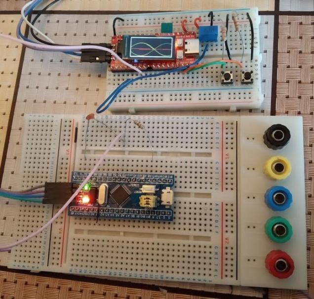
The picture above shows the display when two inputs are used: A steady DC value from a potentiometer and a sine-wave generated by a blue-pill board doing some fast PWM (See this post).
The picture of the display is showing “ghosting” because of the slow shutter speed of the camera.
Two buttons are fitted to the board to allow the user increase and decrease the sample rate which stretches and compresses the waveform on the screen.
This is not meant to be an actually useful instrument – it’s just a learning exercise for this device.
Code is over on github.
Month: January 2020
Fast PWM on the STM32F103 Bluepill
I needed a signal source for another project I’m working on so I set about building a signal generator of sorts using a “Bluepill” board. The STM32F103 on these boards does not have a Digital to Analogue Converter but it does have a very capable timer which can be used to generate waveforms.
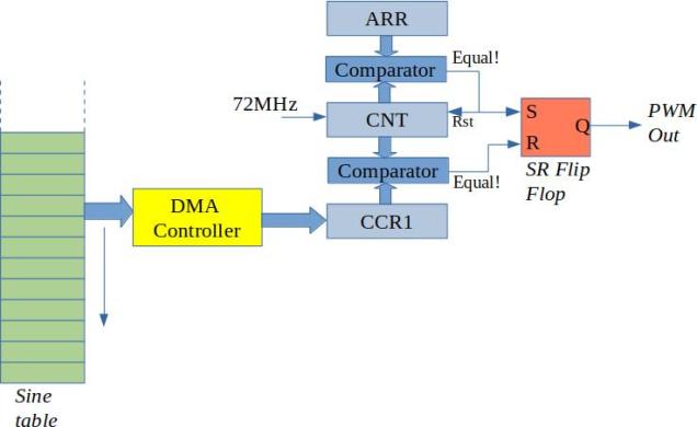
The timer (TIM1) is shown in the diagram above. In the mode that it is configured for this project it works as follows:
The CNT register counts up to the value in ARR
When CNT = ARR the upper digital comparator outputs a pulse which is used to reset CNT to 0 and to set the PWM output signal high (via the S-R Flip-Flop).
When CNT is equal to the value in CCR1, the lower digital comparator outputs a pulse which resets the PWM output low. ARR therefore controls the output frequency while CCR1 controls the output duty.
(CNT = count, ARR = auto-reload register, CCR1 = Counter-Compare Register 1)
I’m interested in producing audio range signals so up to about 20kHz. An trade-off between switching frequency, resolution, and output filtering arises here. First of all, I want to use a simple RC filter on the output to remove the high frequency switching. This means that the switching frequency has to be a lot higher than the target output signal i.e. much greater than 20kHz. But how much higher? The clock in the STM32F103 runs at 72MHz so this places an upper limit on things. Lets say we go for a switching frequency of 12MHz. This means that the counter will count from zero to five and then back up to zero again (6 states in total). This means that our PWM waveform generation system is only able to produce 6 different outputs (between 2 and 3 bits of resolution) which is pretty poor. I wanted a lot more resolution than that so after playing with the numbers I arrived at the following. Let ARR = 255 (8 bits of resolution). This gives a switching frequency of 280500Hz which is certainly not audible and is pretty easy to filter with passive components.
In order to produce a sine-wave output the CCR1 value needs to be varied sinusoidally. This could be done by generating an interrupt for each PWM cycle and loading values from a look-up table into CCR1. This places a reasonably high load on the CPU however given the high switching frequency. Another option is to use DMA which can transfer values from the lookup-table directly into CCR1. After all the values of the table have been used up, the DMA controller can then generate an interrupt allowing the program to perhaps modify the output signal if necessary. The interrupt rate is a lot lower with this approach and the CPU is free to do other tasks.
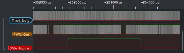
The figure above shows a logic analyzer view of the outputs. The upper signal is a fixed duty signal from CCR2 (another PWM output channel). The middle signal is the sinusoidal PWM output. The lower signal is a digital output that is toggled at the end of each DMA transfer (every millisecond).
After filtering the output looks like this:

The upper trace is the PWM output after it has been passed through an RC filter with a cutoff of 20kHz. As expected the switching frequency (which is most pronounced around zero-crossings of the sinewave) is attenuated to about 1 tenth of its original size. The lower trace shows the unfiltered output.
The next step is to produce a variable frequency and voltage output – perhaps even two channels. Code is available over on github
Incidentally, the particular board used here is one with 128kB of flash (earlier ones I used had only 64kB).
