The Nucleo ST-Link reflashed as a J-Link debugger

ST Microelectronics recently announced that the ST-Link debug interfaces on their boards can be reprogrammed as Segger/J-Link interfaces.  Curious, I flashed the firmware on to such a debugger as directed here https://www.segger.com/jlink-st-link.html .

I then wired the debugger to an stm32f030 as shown in the pictures below (the debugger had been snapped off the Nucleo board because the target MCU had been damaged)
JLink_stm32f030_2

JLink_stm32f030_1

The SWD connections are taken from CN4 and joined to the corresponding pins on the STM32F030.  Note the way the 3.3V is taken from the top of the jumper JP1:  The jumper must remain in place to power the debug interface.

Important: The Boot0 pin must be pulled to ground with a resistor or the CPU will boot to ISP mode and you won’t be able to run your test program.

In addition to the SWD connections, the STM32F030’s UART is connected to the TX and RX pins on the debug interface.  This allows an application running on the STM32F030 to send data to the host PC.

All of this was done in Ubuntu Linux using OpenOCD.  The OpenOCD configuration script (tbrd.cfg) is shown below:


# This is for the STM32F030 connected to the ST-Link Nucleo
# programmer that has been reflashed with the J-Link firmware

source [find interface/jlink.cfg]
transport select swd
source [find target/stm32f0x.cfg]
adapter_khz 1000

reset_config srst_nogate

The debug arrangement worked well: programs loaded quickly, registers could be examined and breakpoints set etc.

To run openocd type the following:

sudo openocd -f tbrd.cfg

In a new terminal window, run arm-none-eabi-gdb

The transcript for a simple session is shown below.

GNU gdb (GNU Tools for ARM Embedded Processors) 7.10.1.20160923-cvs
Copyright (C) 2015 Free Software Foundation, Inc.
License GPLv3+: GNU GPL version 3 or later <http://gnu.org/licenses/gpl.html>
This is free software: you are free to change and redistribute it.
There is NO WARRANTY, to the extent permitted by law.  Type "show copying"
and "show warranty" for details.
This GDB was configured as "--host=i686-linux-gnu --target=arm-none-eabi".
Type "show configuration" for configuration details.
For bug reporting instructions, please see:
<http://www.gnu.org/software/gdb/bugs/>.
Find the GDB manual and other documentation resources online at:
<http://www.gnu.org/software/gdb/documentation/>.
For help, type "help".
Type "apropos word" to search for commands related to "word".
(gdb) target remote :3333
Remote debugging using :3333
0x00000000 in ?? ()
(gdb) monitor reset halt
target state: halted
target halted due to debug-request, current mode: Thread 
xPSR: 0xc1000000 pc: 0x080000b4 msp: 0x20001000
(gdb) load main.elf
Loading section .text, size 0x328 lma 0x8000000
Start address 0x8000000, load size 808
Transfer rate: 3 KB/sec, 808 bytes/write.
(gdb) continue 
Continuing.


Using SPI and DMA to drive 3 WS2812Bs with an STM32F042 Nucleo

As promised in a previous post, this example drives 3 WS2812B’s using DMA to SPI.  It also shows that interrupts can happen at the same time without affecting the performance of the LED’s.

IMG_20160409_213853729

Three LED’s are controlled and, as expected, the burst of SPI data lasts 72 microseconds.

SPIDMAWaveform

The program outputs a simple RGB pattern that moves across the LED’s.  The program is deliberately slowed down to allow us see the changing colours.  The program also outputs a message over the UART to the host PC using an interrupt driven serial transmit routine which demonstrates that the solution is tolerant of interrupts.

A video of the program in action is over on YouTube.

Code may be downloaded over here on Github

STM32F042 driving a WS2812B using SPI

IMG_20160408_173534855

The WS2812B is an RGB LED with a built in serial interface.  They are available from a number of sources.  The ones used in this project were obtained from dx.com and cost about 6 Euro for a pack of 5.  These are mounted on a nice little breakout board.  Pins can be soldered on allowing them to be plugged into a breadboard as shown above.

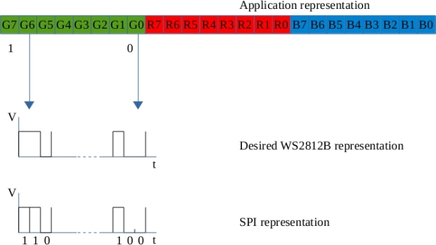
Driving a WS2812B requires some delicate timing.  It has a serial interface that represents 1’s and 0’s using a particular waveform rather than a simple high or low.  A ‘1’ is represented by a high-low pulse with the high pulse lasting about twice as long as the low pulse.  A ‘0’ is represented with a high-low pulse also though in this case, the low pulse is twice the width of the high pulse. The datasheet also specifies maximum and minimum widths for pulses.  Roughly speaking, the high-low waveform must be completed in about a microsecond.  I noticed that there were some solutions online that used SPI to generate the serial waveforms and decided to try it out on the STM32F042 Nucleo.

The first step was to figure out the mapping of RGB colour values to SPI bytes.  Note: The WS2812B orders the colours as Green Red Blue so I will be using the term “GRB colour value” below.  The WS2812B must be sent a 24bit colour value followed by a low signal of a least 50 microseconds.  Conceptually I think of this as filling a 24 bit shift register and then latching the contents through to the LED’s.  The data is translated to SPI bytes as shown below:

bit_conversion

The WS2812B datasheet contains the following specifications for the waveforms.

WS2812B Logic 1:

A high pulse of 0.8us +/-150ns followed by a low pulse of 0.4us +/-150ns

Total width : 1.25us +/-600ns

WS2812B Logic 0:

A high pulse of 0.4us +/-150ns followed by a low pulse of 0.8us +/-150ns

Total width : 1.25us +/-600ns

If the SPI bus is run at 3MHz, one SPI bit lasts 0.333us, two SPI bits take 0.667us. These times are within the WS2812B specification for narrow and wide pulse widths. A colour bit value of ‘1’ in the application layer is mapped to an SPI bit pattern of ‘110’; while a colour bit value of ‘0’ in the application layer is mapped to an SPI bit pattern of ‘100’. Each application colour byte therefore maps to 3 SPI bytes. A 3 byte Green-Red-Blue colour value in the application layer is converted to a 9 byte SPI sequence and output to the WS2812B.

The SPI output (MOSI) is taken from the pin labelled “A6” on the Nucleo board and connected to Din (Data In) on the WS2812B breakout board.

A demonstrator application generates a Green/Red/Blue colour value that changes over time. This value is converted to a 9 byte SPI array and output to the WS2812B. A video showing the colour progression is available on YouTube . Note. The LED is covered with a piece of quartz to dim it a little (the camera didn’t like it being so bright).

Code is available on GitHub and was compiled using arm-gcc 4.9.3.  OpenOCD was used to download and debug.  Next step is to drive a string of these using DMA and SPI 🙂