Low pass filtering using the STML432 Nucleo

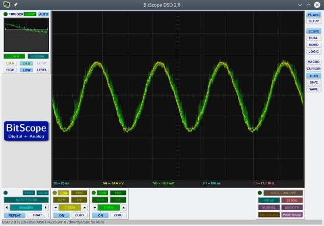
This example uses a 4th order Butterworth low pass filter that was designed in GNU Octave.  The sampling rate was set to 200kHz and the cut-off frequency was set to 20kHz.  The filter output at 20kHz is shown below and, as expected, shows an attenuation of 0.7 (approx the square root of 2).

FilterOutput1

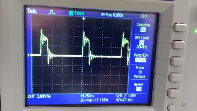
Various attempts were made to optimize the performance of the filter.  The execution time was measured by flipping an output bit either side of the filter code.  An oscilloscope trace of this output is below.

FilterTiming1

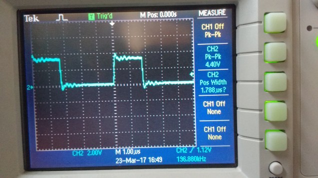
As can be seen, the execution time is 1.78 microseconds. This is pretty quick given that floating point numbers are being used.  I found that my attempts to manually improve the performance made no significant difference compared to what the compiler’s optimizer could do.  I also found that gcc’s -O2 optimization setting produced a faster filter than -O3.  The filter shuffles data in the input and output delay lines.  This may be considered less  than optimal but, given that the order of the filter is low, it probably would make little difference to use circular buffers (and manage buffer state etc).

Code can be downloaded here on Github and should be easily compiled on Linux/Windows/Mac

Analogue pass-through at 1MHz on the STM32L432 Nucleo board

Update: I previously had measured (incorrectly) a conversion rate of 4MHz – on moving to better instrumentation this proved to be incorrect.  The maximum stable conversion rate comes out just below 2MHz.  This example runs the system at 1MHz.20kHz_at_4MHz

The STM32L432KC Nucleo board is a low cost board (approx €13) in the same form factor as an Arduino Nano.  The onboard CPU is based on an ARM Cortex M4F running at 80MHz.  It features a very fast ADC and 2 DAC output as well as a number of timers, serial interfaces and so on.

I was curious to see how fast the ADC could be read using a timer as a trigger so I put together a simple program that reads an analogue input and writes this value back out to the DAC.  The graph above shows two traces:  the output is green and is overlaid on top of the input (yellow).  The input signal is a 20kHz sine wave (DC shifted to 1.5V).  The system is reading the input signal and updating the output at 1MHz.  An interrupt service routine (ISR) is called at each ADC conversion which consists of the following code:


void ADC_ISR()
{
  // The green LED output is used to measure the execution time of the ISR
  GPIOB_ODR |= BIT3;   // Turn on green led
  ADC1_ISR = BIT3;     // clear ADC interrupt flag
  GPIOB_ODR |= BIT3;   // Toggle green led
  ADCValue = ADC1_DR;  // Read latest value from ADC conversion
  writeDAC(ADCValue);  // Write new output to DAC
  GPIOB_ODR &= ~BIT3;  // Turn off green led
}

The onboard LED is driven high at the beginning of the ISR and low again on exit.  This allows a measurement to be made of CPU usage inside the ISR.  I used an oscilloscope to monitor the behaviour of the LED pin and this is shown in the trace below

1MHzSamplingCPUUsage

As can be seen, the CPU is loaded to around 25%

Source code for this example and others is available over here on Github

Compiling should be pretty straightforward:

(1) Run the build script (batch file) on Linux/Windows/Mac.

(2) Plug the nucleo board in to your computer and it should appear as disk

(3) Copy “main.bin” to this new “disk”

This should program the board and start the program running.