In this example a BBC Microbit V2 will be programmed to behave as a step counter and it will report these over its BLE interface. This will not be a primer on Bluetooth. There are plenty of those to be found on the Internet. This post will be specifically about how you work with Zephyr and BLE on the Microbit V2.
BLE Roles for the BBC Microbit and a mobile phone
When your phone connects to a bluetooth device such as a pedometer it takes on a role defined by the Bluetooth SIG as “Central”. The pedometer or other device’s role is “Peripheral”. The central device initiates a connection with the peripheral. The peripheral device can advertise services which contain characteristics that can be read or written. They can also send notifications to the central device should a sensor value change. These services are identified using numeric values. In this example a 128 bit UUID of 00000001-0002-0003-0004-000000000000 is used to identify a step-count service which has a single characteristic (the actual step-count value) with a UUID of 00000001-0002-0003-0004-000000000005
This step count service is defined in Zephyr as follows:
The characteristic contained within this service is defined as follows:
// ********************[ Start of First characteristic ]**************************************
#define BT_UUID_STEPCOUNT_ID  BT_UUID_128_ENCODE(1, 2, 3, 4, (uint64_t)5)
static struct bt_uuid_128 stepcount_id=BT_UUID_INIT_128(BT_UUID_STEPCOUNT_ID); // the 128 bit UUID for this gatt value
uint32_t stepcount_value=0; // the gatt characateristic value that is being shared over BLE
static ssize_t read_stepcount(struct bt_conn *conn, const struct bt_gatt_attr *attr, void *buf, uint16_t len, uint16_t offset);
static ssize_t write_stepcount(struct bt_conn *conn, const struct bt_gatt_attr *attr, const void *buf, uint16_t len, uint16_t offset, uint8_t flags);
// Callback that is activated when the characteristic is read by central
static ssize_t read_stepcount(struct bt_conn *conn, const struct bt_gatt_attr *attr, void *buf, uint16_t len, uint16_t offset)
{
	printk("Got a read %d\n",stepcount_value);
	const char *value = (const char *)&stepcount_value; // point at the value in memory
	return bt_gatt_attr_read(conn, attr, buf, len, offset, value, sizeof(stepcount_value)); // pass the value back up through the BLE stack
}
// Callback that is activated when the characteristic is written by central
static ssize_t write_stepcount(struct bt_conn *conn, const struct bt_gatt_attr *attr,
			 const void *buf, uint16_t len, uint16_t offset,
			 uint8_t flags)
{
	uint8_t *value = attr->user_data;
	printk("Got a write %d\n",len);
	if (len == sizeof(stepcount_value)) // check that the incoming data is the correct size
	{
		memcpy(value, buf, len); // copy the incoming value in the memory occupied by our characateristic variable
	}
	else
	{
		printk("Write size is incorrect.  Received %d bytes, need %d\n",len,sizeof(stepcount_value));
	}
	return len;
}
// Arguments to BT_GATT_CHARACTERISTIC = _uuid, _props, _perm, _read, _write, _value
#define BT_GATT_CHAR1 BT_GATT_CHARACTERISTIC(&stepcount_id.uuid,BT_GATT_CHRC_READ | BT_GATT_CHRC_WRITE |  BT_GATT_CHRC_NOTIFY, 	BT_GATT_PERM_READ | BT_GATT_PERM_WRITE, read_stepcount, write_stepcount, &stepcount_value)
// ********************[ End of First characteristic ]****************************************
As you can see from both of these definitions there are lots of C-macros involved. These are included to help the developer avoid some of the lower level details. The characteristic stores its value in the integer stepcount_value. The characteristic is defined as having the following properties: Read, Write and Notify.
If the central device issues a read requent then the function read_stepcount is called. This function copies the the contents of stepcount_value to a buffer (buf) which is then passed back to the central device.
If the central device writes to the microbit the function write_stepcount will be called. This copies data from a buffer passed by the lower level of the BLE stack into the memory occupied by stepcount_value.
void main(void)
{
	int err;
	int old_stepcount = 0;
	err = lsm303_ll_begin();
	if (err < 0)
	{
		 printk("\nError initializing lsm303.  Error code = %d\n",err);
         while(1);

	}
	err = bt_enable(NULL);
	if (err) {
		printk("Bluetooth init failed (err %d)\n", err);
		return;
	}
	bt_ready(); // This function starts advertising
	bt_conn_cb_register(&conn_callbacks);
	printk("Zephyr Microbit V2 minimal BLE example! %s\n", CONFIG_BOARD);
	if (lsm303_countSteps(&stepcount_value) < 0)
	{
		printk("Error starting step counter\n");
		while(1);
	}

	while (1) {
		k_msleep(100);
		// int bt_gatt_notify(struct bt_conn *conn, const struct bt_gatt_attr *attr, const void *data, u16_t len)
		// conn: Connection object. (NULL for all)
		// attr: Characteristic Value Descriptor attribute.
		// data: Pointer to Attribute data.
		// len: Attribute value length.
		if (active_conn)
		{
			if (stepcount_value != old_stepcount) // only send a notification if the data changes
			{
				old_stepcount = stepcount_value;
				bt_gatt_notify(active_conn,&my_service_svc.attrs[2], &stepcount_value,sizeof(stepcount_value));
			}
		}
	}
}
It begins by initializing the LSM303 accelerometer on the Microbit. It then starts bluetooth advertising. The main loop sleeps for 100ms and then sends an update to the central device if there is an active BLE connection and if there has been a change to the step-count value.
Some significant changes need to be made to prj.conf to enable Bluetooth. On such change is this:
CONFIG_BT_DEVICE_NAME=”Microbit V2 BLE”
This allows you set the name that the microbit will broadcast when advertising its presence.
Note: all examples used in this tutorial can be found in full over here on github
When should you use an operating system?
There is no simple answer here other than this : “When the value it provides is greater than the cost of learning and using it”.
Among the value offerings of operating systems is hardware abstraction, complex library support, communications protocols and security. Developing these features/libraries from scratch is error prone and time consuming. There is no doubt that you will bring a product to market faster by using a good existing OS and it is likely that your maintenance burden will be reduced. You may also find it easier to recruit developers for such an OS in contrast to using a home-grown solution. That said, using an OS, even a free one, is not cost free. You will have to set up a development environment, learn about it’s libraries and API’s and possibly live with a bigger memory footprint, I/O timing jitter, and a higher CPU load. This may then cause you to raise the hardware specification of your MCU. Elicia White, author of Embedded Systems advises that you should consider using an OS for your MCU project once you get into the realms of networking and/or USB. This application domain is IoT so we will take that advice and base our application on an existing embedded operating system.
Choosing an OS
Factors affecting your choice: Cost, Code size (Flash memory), RAM usage, Hardware support, ongoing support and updates, licensing, value added features such as integration with IoT services such as remote firmware update and messaging. In the case of the BBC Microbit V2 there are not that many options for an embedded OS. The MCU at the heart of the Microbit-V2 is an NRF52833 from Nordic semiconductors. Nordic provides a “binary blob” to manage the radio interface and other hardware elements (this is referred to as a soft-device). In many ways this resembles an operating system. Application developers link this blob with their code and interact with it using an API. Embedded operating systems on this platform also interact with the soft-device and provide an additional range of services. Embedded OS options for the NRF52833 include:
FreeRTOS, Zephyr, and Riot OS (there may be more). Of these Zephyr stood out as having a very active development community. It is licensed using the Apache 2.0 license which is quite permissive. Nordic Semiconductors also seem to be actively supporting this OS so for these reasons, Zephyr was chosen.
What is Zephyr?
Zephyr is a designed to run on microcontrollers with a limited amount of ROM, RAM and CPU resources. It targets a range of MCU cores including various ARM devices, Intel x86, RISC-V and ESP32. This means that application development skills you acquire on one hardware platform can be transferred to other devices.
When we use the phrase “Operating System” we may be inclined to think of desktop operating systems such as Windows, OS-X, Linux etc. Desktop OS’s allow you load and run programs dynamically. Embedded operating systems such as Zephyr do not work like this. The OS and application are compiled together into one single file which is programmed on the target device. When the system starts up, the OS is booted and your application runs. Typically, your application is the only one running on the target system (it may have multiple threads but that’s another story). In this sense, you can consider OS’s such as Zephyr to be like a library that you might link with your own code.
Setting up a working environment.
In order to build applications for Zephyr you need to set up a compiler, libraries, header files and a host of other tools. This environment is sometimes referred to as a toolchain. Detailed instructions for setting up Zephyr on your computer are available here: https://docs.zephyrproject.org/latest/getting_started/index.html
Note: At the end of the installation instructions you are told to test your toolchain and board by compiling a simple blinking LED example. This will not work with the Microbit-V2 as there is no “simple” user LED on the board. You can however build the hello world example as follows:
west build -p auto -b bbc_microbit_v2 samples/hello_world –pristine
The output from this program is sent to your PC using a built-in USB-Serial converter in the Microbit. On Linux this will appear as device /dev/ttyACM0 typically. On Windows this will appear as COM3 or similar. Run a dumb terminal application with a baud-rate of 115200bps, 8 data bits and no parity and you should hopefully see the output on you PC screen.
The BBC Microbit (V2) hardware
The Microbit V2 has a number of built-in peripherals that are accessible by the programmer. These are shown above. The LED matrix is a arranged in a 5 row by 5 column matrix with one GPIO (GPIO= General Purpose Input Output port) row pin supplying (sourcing) current and a GPIO column pin absorbing (sinking) current. There are also two push buttons which are pulled high via 10k resistors; when a button is pressed it pulls a GPIO pin low. The edge connector provides access to GPIO pins some of which are also used by the onboard peripherals. So, if you plan to use an edge connector pin be sure that it does not interfere with an onboard peripheral that you also intend to use.
The onboard LSM303AGR is a 3 axis accelerometer and 3 axis magnetometer. It is used for motion sensing. It is connected to the NRF52833 via an I2C bus (signals can be viewed on board test points)
Zephyr and I/O pins.
Zephyr uses the a system called devicetree to identify GPIO pins, I2C devices and other peripherals. It is quite confusing for beginners (like me) to use and makes extensive use of C macros. In an effort to avoid turning this into a tutorial on devicetree the example projects will make minimal use of devicetree and will instead use Zephyr API’s to access I/O where possible.
Making patterns on the LED matrix
The full code for this example is in the project led_matrix
The LED matrix is wired as shown above. The Input/Output list is as follows:
Signal
Port
Bit
Source/Sink
ROW1
GPIO0
21
Source
ROW2
GPIO0
22
Source
ROW3
GPIO0
15
Source
ROW4
GPIO0
24
Source
ROW5
GPIO0
19
Source
COL1
GPIO0
28
Sink
COL2
GPIO0
11
Sink
COL3
GPIO0
31
Sink
COL4
GPIO1
5
Sink
COL5
GPIO0
30
Sink
All of these pins must be configured as outputs (because your program will set them high or low). The Source pins must be a High to light an LED and the Sink pins must be Low.
The matrix can be configured in code as follows:
#define ROW1_PORT_BIT 21
#define ROW2_PORT_BIT 22
#define ROW3_PORT_BIT 15
#define ROW4_PORT_BIT 24
#define ROW5_PORT_BIT 19

#define COL1_PORT_BIT 28
#define COL2_PORT_BIT 11
#define COL3_PORT_BIT 31
#define COL4_PORT_BIT 5
#define COL5_PORT_BIT 30

static const struct device *gpio0, *gpio1;
int matrix_begin()
{
    int ret;
    // Configure the GPIO's
    gpio0=device_get_binding("GPIO_0");
    if (gpio0 == NULL)
    {
        printf("Error acquiring GPIO 0 interface\n");
        return -1;
    }
    gpio1=device_get_binding("GPIO_1");
    if (gpio0 == NULL)
    {
        printf("Error acquiring GPIO 1 interface\n");
        return -2;
    }
    ret = gpio_pin_configure(gpio0,ROW1_PORT_BIT,GPIO_OUTPUT);
    ret = gpio_pin_configure(gpio0,ROW2_PORT_BIT,GPIO_OUTPUT);
    ret = gpio_pin_configure(gpio0,ROW3_PORT_BIT,GPIO_OUTPUT);
    ret = gpio_pin_configure(gpio0,ROW4_PORT_BIT,GPIO_OUTPUT);
    ret = gpio_pin_configure(gpio0,ROW5_PORT_BIT,GPIO_OUTPUT);

    ret = gpio_pin_configure(gpio0,COL1_PORT_BIT,GPIO_OUTPUT);
    ret = gpio_pin_configure(gpio0,COL2_PORT_BIT,GPIO_OUTPUT);
    ret = gpio_pin_configure(gpio0,COL3_PORT_BIT,GPIO_OUTPUT);
    ret = gpio_pin_configure(gpio1,COL4_PORT_BIT,GPIO_OUTPUT);
    ret = gpio_pin_configure(gpio0,COL5_PORT_BIT,GPIO_OUTPUT);

    matrix_all_off();
    return 0;
}
The Zephyr API calls used are:
get_device_binding and gpio_pin_configure
The first of these get_device_binding returns a pointer to a Zephyr device structure. The behavior is similar to the file open function fopen in C. If the device can’t be found a null is returned otherwise you use the returned value for future operations on that device. The argument passed to get_device_binding is GPIO_0 (and later GPIO_1). This string is used to search the device tree and if a matching device label is found the function returns a pointer to it’s device structure. So the first few lines of matrix_begin retrieve pointers to the gpio0 and gpio1 devices.
The gpio_pin_configure function takes three arguments:
A pointer to the device structure for that GPIO port
Once again, three arguments are required: you must tell it the port, the bit number and whether the pin is to be High (1) or Low (0).
The function below can be used to put a pattern on the matrix. The row and column states are passed as the 5 least significant bits of the rows and cols parameters.
Finally, here is the main function that generates the matrix pattern. Note the inversion of the cols variable in the call to matrix_put_pattern. This is because column bits are active low (they sink current).
Other bits on the edge connector can be used in a similar way. For example looking at the extract from the Microbit V2 schematic below we can see that P2 or Ring 0 is connected to GPIO port 0, bit 2.
Reading inputs.
The Microbit has two push buttons that pull low when pushed. The configuration of these inputs follows the same pattern as the outputs above. First identify the port and bit number involved and use gpio_pin_configure to configure them as digital inputs (GPIO_INPUT). To read a pin state we call on gpio_pin_get passing two arguments: a pointer to the port device structure and the bit number in question. The function will return 0 or 1 depending on the pin state or and error code (negative value ) if something went wrong.
// Both buttons are on GPIO0
#define BUTTON_A_PORT_BIT 14
#define BUTTON_B_PORT_BIT 23
static const struct device *gpio0;
int get_buttonA()
{
    return gpio_pin_get(gpio0,BUTTON_A_PORT_BIT);
}
int get_buttonB()
{
    return gpio_pin_get(gpio0,BUTTON_B_PORT_BIT);
}
int buttons_begin()
{
    int ret;
    // Configure the GPIO's
    gpio0=device_get_binding("GPIO_0");
    if (gpio0 == NULL)
    {
        printf("Error acquiring GPIO 0 interface\n");
        return -1;
    }
    ret = gpio_pin_configure(gpio0,BUTTON_A_PORT_BIT,GPIO_INPUT);
    ret = gpio_pin_configure(gpio0,BUTTON_B_PORT_BIT,GPIO_INPUT);
    return 0;
}

void main(void)
{
    int ret;
    uint8_t rows = 1;
    uint8_t cols = 1;
    ret = matrix_begin();
    if (ret < 0)
    {
        printf("\nError initializing LED matrix.  Error code = %d\n",ret);
        while(1);
    }
    ret = buttons_begin();
    if (ret < 0)
    {
        printf("\nError initializing buttons.  Error code = %d\n",ret);
        while(1);
    }
    while(1)
    {
        matrix_put_pattern(rows, ~cols);
        if (get_buttonA()==0)
        {
            cols = cols << 1; // only change pattern when button A pressed
        }
        if (get_buttonB()==0)
        {
            rows = cols = 1; // reset pattern to start condition
        }
        if (cols > 16)
        {
            cols = 1;
            rows = rows << 1;
            if (rows > 16)
            {
                rows = 1;
            }
        }
        k_msleep(100);
    }
}
The full code for this example is in the project buttons_with_matrix
The above example uses “polling” i.e. continuous reading of the state of the inputs to decide what to do. This is inefficient as the CPU is running at full speed and may miss inputs if it is doing some other task. An alternative approach is to use interrupts which will trigger the execution of a particular function (the interrupt handler) when a hardware event occurs. If the CPU is busy doing something else this task will be suspended while the interrupt handler executes (so long as interrupts have been enabled. The example below is a modification of the above button code.
static fptr button_a_user_handler = NULL;
static struct gpio_callback button_a_cb;
static void button_a_handler(const struct device *dev, struct gpio_callback *cb, uint32_t pins)
{
    printk("interrupt\n");
    if (button_a_user_handler)
    {
        button_a_user_handler();
    }
}
int attach_callback_to_button_a(fptr callback_function)
{
    if (gpio_pin_interrupt_configure(gpio0,BUTTON_A_PORT_BIT,GPIO_INT_EDGE_FALLING) < 0)
    {
        printk("Error configuring interrupt for button A\n");
    }
    gpio_init_callback(&button_a_cb, button_a_handler, (1 << BUTTON_A_PORT_BIT) );
    if (gpio_add_callback(gpio0, &button_a_cb) < 0)
    {
        printk("Error adding callback for button A\n");
    }
    else
    {
        // success so far so use the user supplied callback function
        button_a_user_handler = callback_function;
    }
    return 0;
}
The function gpio_pin_interrupt_configure takes three arguments: a reference to the GPIO port, the bit number in question and a flag to indicate whether you want to be interrupted on falling or rising edges etc.
The function gpio_init_callback is used to prepare a structure of type gpio_callback which will be used in a follow-on call to the gpio_add_callback function. gpio_init_callback takes three arguments: the address of the structure that will be prepared, the address of the function that will handle the callback and bitmask identifying which pins will trigger the callback (note the difference between the third parameter here and the second parameter for gpio_pin_interrupt_configure).
The function gpio_add_callback is the last step in setting up interrupts. It takes two arguments : a reference to the GPIO port and the structure that was prepared by gpio_init_callback.
Following all of this, when a falling edge (a button press) happens the function button_a_handler will be called automatically. The declaration of this function is a little complex so I have decided to hide this from the typical user. Instead, the user calls on attach_callback_to_button_a and passes the address of a function they would like called when the button is pressed. This address is stored and when button_a_handler is activated it will call the user function there.
The main function matching this example is shown below.
The full code for this example is in the project buttons_with_matrix_with_interrupts
Note the use call to attach_callback_to_button_a takes a single argument – the address of the function you would like to run. In this case, the callback function moves the led matrix pattern variables along a step each time the button is pressed. Also note the use of the volatile keyword.
I was in touch with the Zephyr developers about a bug in the driver for the magnetometer used on the BBC microbit. They kindly fixed it and I have modified my previous magnetometer example. I have also been working on a stripped down BLE example which provides a single service with a single Read/Write/Notify characteristic. The original zephyr set of examples has a very good but also quite complex BLE example. The example makes use of lots of macros that construct various structures and arrays. These can be a little daunting for a beginner. I have tried to remove anything that is non-essential for this example and have added additional comments and references to header files and web resources that will hopefully explain what is going on a little better.
The listing for main.c is shown below. The full set of examples is over here on github. Feel free to post questions in the comments section.
/* main.c - Application main entry point */

/* Based on an example from Zephyr toolkit, modified by frank duignan
 * Copyright (c) 2015-2016 Intel Corporation
 *
 * SPDX-License-Identifier: Apache-2.0
 */
/* This example advertises three services:
 * 0x1800 Generic ACCESS (GAP)
 * 0x1801 Generic Attribute (GATT - this is part of the software device and is not used nor is it apparently removable see https://devzone.nordicsemi.com/f/nordic-q-a/15076/removing-the-generic-attribute-0x1801-primary-service-if-the-service-changed-characteristic-is-not-present
 * And a custom service 1-2-3-4-0
 * This custom service contains a custom characteristic called char_value
 */
#include <zephyr/types.h>
#include <stddef.h>
#include <string.h>
#include <errno.h>
#include <sys/printk.h>
#include <sys/byteorder.h>
#include <zephyr.h>

#include <settings/settings.h>

#include <bluetooth/bluetooth.h>
#include <bluetooth/hci.h>
#include <bluetooth/conn.h>
#include <bluetooth/uuid.h>
#include <bluetooth/gatt.h>
#include <device.h>
#include <drivers/sensor.h>
#include <stdio.h>


#define BT_UUID_CUSTOM_SERVICE_VAL BT_UUID_128_ENCODE(1, 2, 3, 4, (uint64_t)0)
static struct bt_uuid_128 my_service_uuid = BT_UUID_INIT_128( BT_UUID_CUSTOM_SERVICE_VAL);
static struct bt_uuid_128 char_id=BT_UUID_INIT_128(BT_UUID_128_ENCODE(1, 2, 3, 4, (uint64_t)5)); // the 128 bit UUID for this gatt value
uint32_t char_value; // the gatt characateristic value that is being shared over BLE
static ssize_t read_char(struct bt_conn *conn, const struct bt_gatt_attr *attr, void *buf, uint16_t len, uint16_t offset);
static ssize_t write_char(struct bt_conn *conn, const struct bt_gatt_attr *attr, const void *buf, uint16_t len, uint16_t offset, uint8_t flags);

/* The bt_data structure type:
 * {
 * 	uint8_t type : The kind of data encoded in the following structure
 * 	uint8_t data_len : the length of the data encoded
 * 	const uint8_t *data : a pointer to the data
 * }
 * This is used for encoding advertising data
*/
/* The BT_DATA_BYTES macro
 * #define BT_DATA_BYTES(_type, _bytes...) BT_DATA(_type, ((uint8_t []) { _bytes }), sizeof((uint8_t []) { _bytes }))
 * #define BT_DATA(_type, _data, _data_len) \
 *       { \
 *               .type = (_type), \
 *               .data_len = (_data_len), \
 *               .data = (const uint8_t *)(_data), \
 *       }
 * BT_DATA_UUID16_ALL : value indicates that all UUID's are listed in the advertising packet
*/
// bt_data is an array of data structures used in advertising. Each data structure is formatted as described above
static const struct bt_data ad[] = {
	BT_DATA_BYTES(BT_DATA_FLAGS, (BT_LE_AD_GENERAL | BT_LE_AD_NO_BREDR)), /* specify BLE advertising flags = discoverable, BR/EDR not supported (BLE only) */
	BT_DATA_BYTES(BT_DATA_UUID128_ALL, BT_UUID_CUSTOM_SERVICE_VAL /* A 128 Service UUID for the our custom service follows */),
};

/*
 * #define BT_GATT_CHARACTERISTIC(_uuid, _props, _perm, _read, _write, _value)
 *
 */
BT_GATT_SERVICE_DEFINE(my_service_svc,
	BT_GATT_PRIMARY_SERVICE(&my_service_uuid),
		BT_GATT_CHARACTERISTIC(&char_id.uuid,
		BT_GATT_CHRC_READ | BT_GATT_CHRC_WRITE |  BT_GATT_CHRC_NOTIFY,
		BT_GATT_PERM_READ | BT_GATT_PERM_WRITE,
		read_char, write_char, &char_value),
);


struct bt_conn *active_conn=NULL; // use this to maintain a reference to the connection with the central device (if any)


// Callback that is activated when the characteristic is read by central
static ssize_t read_char(struct bt_conn *conn, const struct bt_gatt_attr *attr, void *buf, uint16_t len, uint16_t offset)
{
	printf("Got a read %p\n",attr);
	// Could use 'const char *value =  attr->user_data' also here if there is the char value is being maintained with the BLE STACK
	const char *value = (const char *)&char_value; // point at the value in memory
	return bt_gatt_attr_read(conn, attr, buf, len, offset, value, sizeof(char_value)); // pass the value back up through the BLE stack
}
// Callback that is activated when the characteristic is written by central
static ssize_t write_char(struct bt_conn *conn, const struct bt_gatt_attr *attr,
			 const void *buf, uint16_t len, uint16_t offset,
			 uint8_t flags)
{
	uint8_t *value = attr->user_data;
	printf("Got a write\n");
	memcpy(value, buf, len); // copy the incoming value in the memory occupied by our characateristic variable
	return len;
}
// Callback that is activated when a connection with a central device is established
static void connected(struct bt_conn *conn, uint8_t err)
{
	if (err) {
		printk("Connection failed (err 0x%02x)\n", err);
	} else {
		printk("Connected\n");
		active_conn = conn;
	}
}
// Callback that is activated when a connection with a central device is taken down
static void disconnected(struct bt_conn *conn, uint8_t reason)
{
	printk("Disconnected (reason 0x%02x)\n", reason);
	active_conn = NULL;
}
// structure used to pass connection callback handlers to the BLE stack
static struct bt_conn_cb conn_callbacks = {
	.connected = connected,
	.disconnected = disconnected,
};
// This is called when the BLE stack has finished initializing
static void bt_ready(void)
{
	int err;
	printk("Bluetooth initialized\n");

// start advertising see https://developer.nordicsemi.com/nRF_Connect_SDK/doc/latest/zephyr/reference/bluetooth/gap.html
/*
 * Excerpt from zephyr/include/bluetooth/bluetooth.h

 * #define BT_LE_ADV_CONN_NAME BT_LE_ADV_PARAM(BT_LE_ADV_OPT_CONNECTABLE | \
                                            BT_LE_ADV_OPT_USE_NAME, \
                                            BT_GAP_ADV_FAST_INT_MIN_2, \
                                            BT_GAP_ADV_FAST_INT_MAX_2, NULL)

 Also see : zephyr/include/bluetooth/gap.h for BT_GAP_ADV.... These set the advertising interval to between 100 and 150ms

 */
// Start BLE advertising using the ad array defined above
	err = bt_le_adv_start(BT_LE_ADV_CONN_NAME, ad, ARRAY_SIZE(ad), NULL, 0);
	if (err) {
		printk("Advertising failed to start (err %d)\n", err);
		return;
	}
	printk("Advertising successfully started\n");
}

void main(void)
{
	int err;

	err = bt_enable(NULL);
	if (err) {
		printk("Bluetooth init failed (err %d)\n", err);
		return;
	}

	bt_ready();
	bt_conn_cb_register(&conn_callbacks);
	printk("Zephyr Microbit V2 minimal BLE example! %s\n", CONFIG_BOARD);
	while (1) {
		k_sleep(K_SECONDS(1));
		char_value++;
		// int bt_gatt_notify(struct bt_conn *conn, const struct bt_gatt_attr *attr, const void *data, u16_t len)
		// conn: Connection object. (NULL for all)
		// attr: Characteristic Value Descriptor attribute.
		// data: Pointer to Attribute data.
		// len: Attribute value length.
		if (active_conn)
		{
			bt_gatt_notify(active_conn,&my_service_svc.attrs[2], &char_value,sizeof(char_value));
		}
	}
}
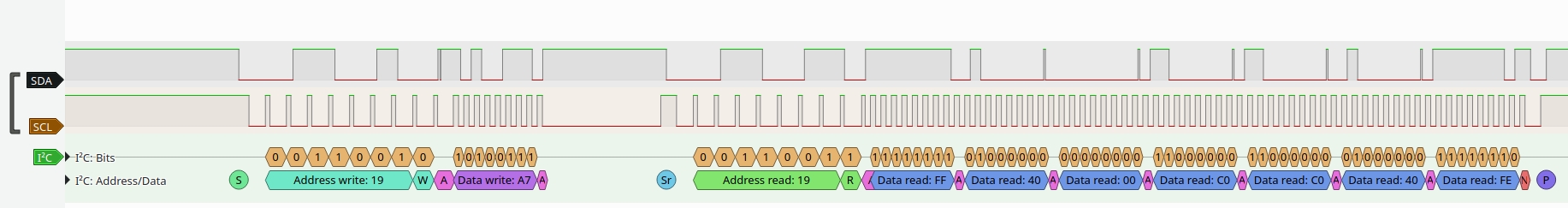
The BBC Microbit V2’s I2C interface usage is different to it’s predecessor. It has two I2C interfaces : an internal one to talk to the on-board accelerometer/magnetometer and an external one for user supplied sensors. Traffic on the internal I2C bus is only visible on tespoints (TP20 and TP21). This makes it difficult to debug/view the internal I2C bus traffic. I had no springloaded test pins to press on to the testpoints so a quick hack as shown above provides just enough pressure on the pads to make an electrical connection. The orange and purple wires are coiled like a spring which causes them to press into the board. These wires are then connected to a logic analyzer via the breadboard. The analyzer displays the following data:
The I2C clock frequency seems to be 400kHz. There appears to be some kind of clock stretching going on also. The trace shows a read from the on-board accelerometer.