The PSRAM64H is a 3.3V 8MByte RAM device that is accessed using SPI (datasheet here). It can operate at speeds of up to 133MHz (though 84MHz is a more realistic top-end value). I’m using it at 5MHz just so that my knock-off cheap logic analyser can keep up with it.

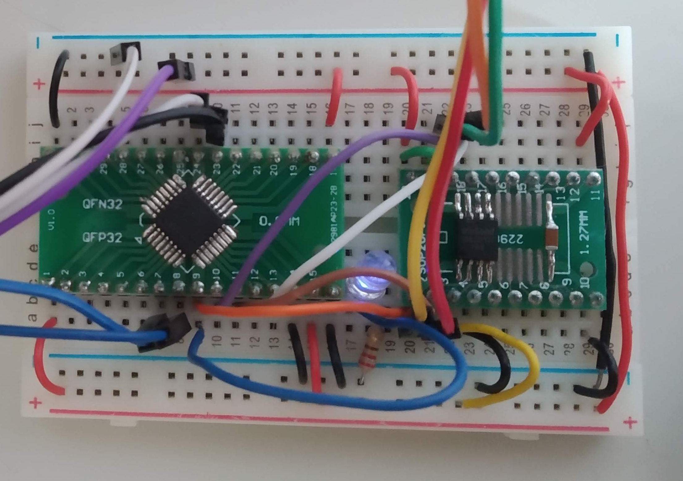
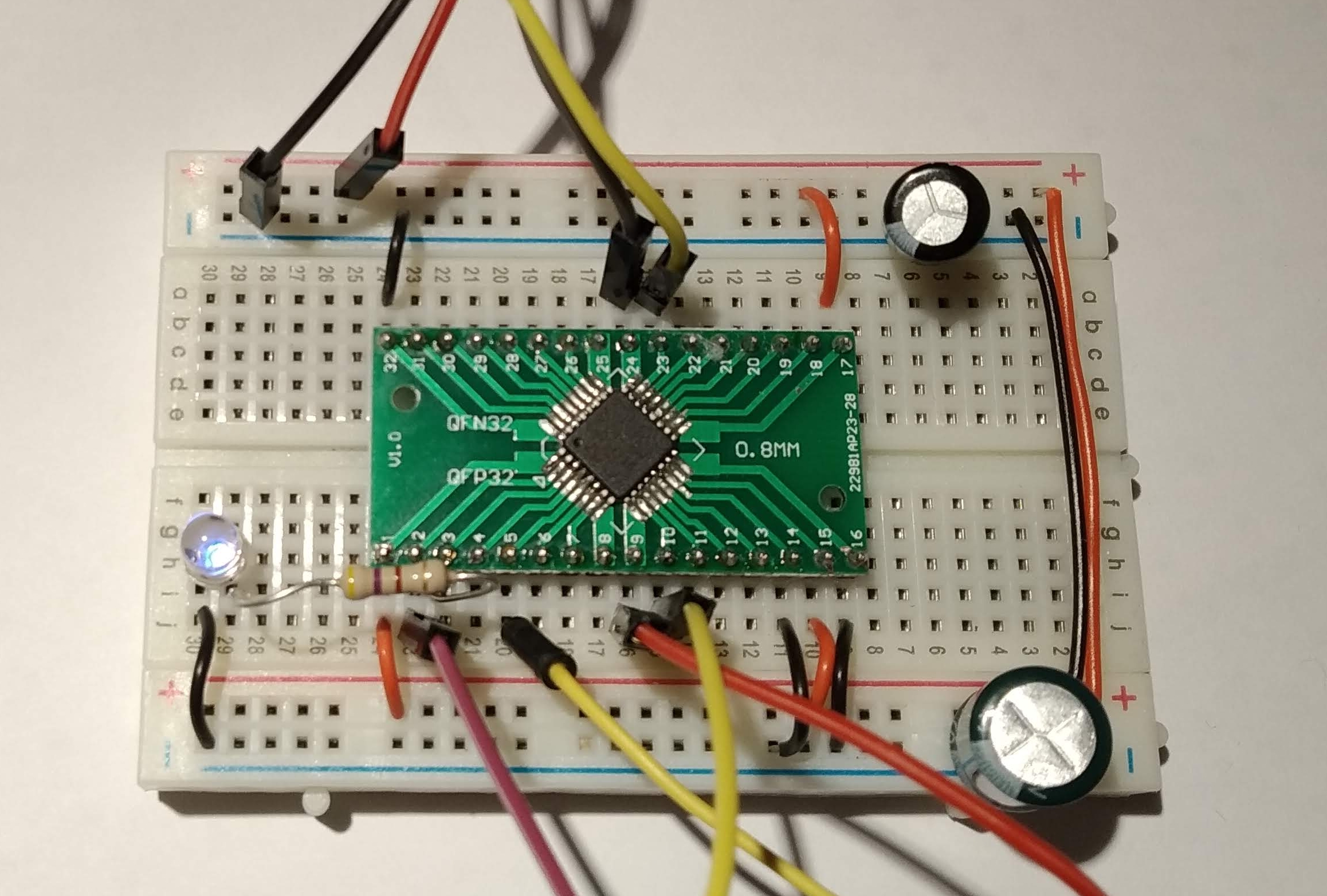
The picture above shows my test layout. The PSRAM64H is mounted on a breakout board so that it can be used in breadboard with the STM32G431.
The test code is shown below. It uses SPI2 on the STM32 device. After initialization, the main loop reads the chip ID and writes 256 bytes to PSRAM starting at address 0x123456. It then reads back data from the same address. If the received data does not match the transmitted data then the LED is turned on.
// Program to interact with the PSRAM64H IC from Espressif


/* IO LIST
 * Will use simple SPI (not QSPI) in this example.
 * PSRAM64H         STM32G431
 * CE#             SPI2 NSS  Pin 2 (PF0)   = AF5
 * CLK             SPI2 SCK  Pin 3 (PF1)   = AF5
 * SI/SIO(0) MOSI  SPI2 MOSI Pin 21 (PA11) = AF5
 * SO/SIO(1) MISO  SPI2 MISO Pin 20 (PA10) = AF5
 *
 * LED             Pin 5 (PA0)
*/

#include <stdint.h>
#include "../include/STM32G431xx.h"
void enablePullUp(GPIO_Type *Port, uint32_t BitNumber)
{
	Port->PUPDR = Port->PUPDR &~(3u << BitNumber*2); // clear pull-up resistor bits
	Port->PUPDR = Port->PUPDR | (1u << BitNumber*2); // set pull-up bit
}
void pinMode(GPIO_Type *Port, uint32_t BitNumber, uint32_t Mode)
{
	/*
        Modes : 00 = input
                01 = output
                10 = special function
                11 = analog mode
	*/
	uint32_t mode_value = Port->MODER;
	Mode = Mode << (2 * BitNumber);
	mode_value = mode_value & ~(3u << (BitNumber * 2));
	mode_value = mode_value | Mode;
	Port->MODER = mode_value;
}
void selectAlternateFunction (GPIO_Type *Port, uint32_t BitNumber, uint32_t AF)
{
    // The alternative function control is spread across two 32 bit registers AFR[0] and AFR[1]
    // There are 4 bits for each port bit.
    if (BitNumber < 8)
    {
        Port->AFR[0] &= ~(0x0f << (4*BitNumber));
        Port->AFR[0] |= (AF << (4*BitNumber));
    }
    else
    {
        BitNumber = BitNumber - 8;
        Port->AFR[1] &= ~(0x0f << (4*BitNumber));
        Port->AFR[1] |= (AF << (4*BitNumber));
    }
}
void spi_startTransaction(void)
{
	SPI2->CR1 |= (1 << 6); // Enable SPI (SPE = 1)

}
void spi_stopTransaction(void)
{
	volatile unsigned Timeout = 1000;
	while (SPI2->SR & ((1 << 12) + (1 << 11)) );     // wait for fifo to empty
	while (((SPI2->SR & (1 << 0))!=0)&&(Timeout--)); // Wait for RXNE
	Timeout = 1000;
	while (((SPI2->SR & (1 << 1))==0)&&(Timeout--)); // Wait for TXE
	Timeout = 1000;
	while (((SPI2->SR & (1 << 7))!=0)&&(Timeout--)); // Wait for Busy
	SPI2->CR1 &= ~(1 << 6); // Disable SPI (SPE = 0)

	while((GPIOF->IDR & (1 << 0))==0); // wait for NSS to go high

}
uint8_t spi_transfer(uint8_t data)
{

    *((uint8_t*)&SPI2->DR) = data;
	while (((SPI2->SR & (1 << 7))!=0));// Wait for Busy
	return *((uint8_t*)&SPI2->DR);
}
void delay(uint32_t dly)
{
    while(dly--);
}
void writePSRAM(uint32_t address, void *data, uint32_t nbytes)
{
    uint8_t b;
    spi_startTransaction();
    spi_transfer(0x02);
    b=address>>16;
    spi_transfer(b);
    b=(address>>8)&0xff;
    spi_transfer(b);
    b=(address)&0xff;
    spi_transfer(b);
    while(nbytes--)
    {
        b=*((uint8_t*)data);
        spi_transfer(b);
        data++;
    }
    spi_stopTransaction();
}
void readPSRAM(uint32_t address, void *data, uint32_t nbytes)
{
    uint8_t b;
    spi_startTransaction();
    spi_transfer(0x03);
    b=address>>16;
    spi_transfer(b);
    b=(address>>8)&0xff;
    spi_transfer(b);
    b=(address)&0xff;
    spi_transfer(b);
    while(nbytes--)
    {
        b=spi_transfer(0xff);
        *((uint8_t*)data)=b;
        data++;
    }
    spi_stopTransaction();

}
uint32_t readIDPSRAM(void)
{
    uint32_t id;
    spi_startTransaction();
    spi_transfer(0x9f);
    spi_transfer(0xff);
    spi_transfer(0xff);
    spi_transfer(0xff);
    id=spi_transfer(0xff);
    id=id<<8;
    id=id+spi_transfer(0xff);
    spi_stopTransaction();
    return id;
}
uint8_t data_out[2048];
uint8_t data_in[2048];
uint32_t chip_id;
int main()
{
    uint32_t count,drain;

    uint32_t error_count;
    RCC->AHB2ENR |= (1 << 0) | (1 << 5); // enable Port A and Port F
    pinMode(GPIOA,0,1);
    pinMode(GPIOA,10,2);
    pinMode(GPIOA,11,2);
    pinMode(GPIOF,0,2);
    pinMode(GPIOF,1,2);
    selectAlternateFunction(GPIOA,10,5);
    selectAlternateFunction(GPIOA,11,5);
    selectAlternateFunction(GPIOF,0,5);
    selectAlternateFunction(GPIOF,1,5);
    RCC->APB1ENR1 |= (1 << 14); // enable SPI2
    // set port bits up as high speed outputs
    GPIOA->OSPEEDR |= (3 << 2*10) + (3 << 2*11);
    GPIOF->OSPEEDR |= (3 << 0) + (3 << 2*1);
    drain = SPI1->SR;				// dummy read of SR to clear MODF
	// enable SSM, set SSI, enable SPI, PCLK/2, MSB First Master, Clock = 1 when idle
	// Will use hardware slave management
	SPI2->CR1 = (1 << 5) + (1 << 2)+ (1 << 1) + (1 << 0); // Master mode, about 5MHz.  CPHA=CPOL=1
	SPI2->CR2 = (1 << 12) + (1 << 10) + (1 << 9) + (1 << 8) + (1 << 2); 	// SS output enabled, 8 bit mode

    for (count=0;count<2048;count++)
        data_out[count]=count;
    while(1)
    {

        chip_id=readIDPSRAM();
        error_count=0;
        writePSRAM(0x123456,data_out,2048);
        readPSRAM(0x123456,data_in,2048);
        for (count=0;count<2020;count++)
        {
            if (data_in[count]!=data_out[count])
            {
                error_count++;
            }
        }
        if (error_count==0)
        {
            GPIOA->ODR &= ~1;
        }
        else
        {
            GPIOA->ODR |= 1;
        }
        delay(1000000);

    }
}
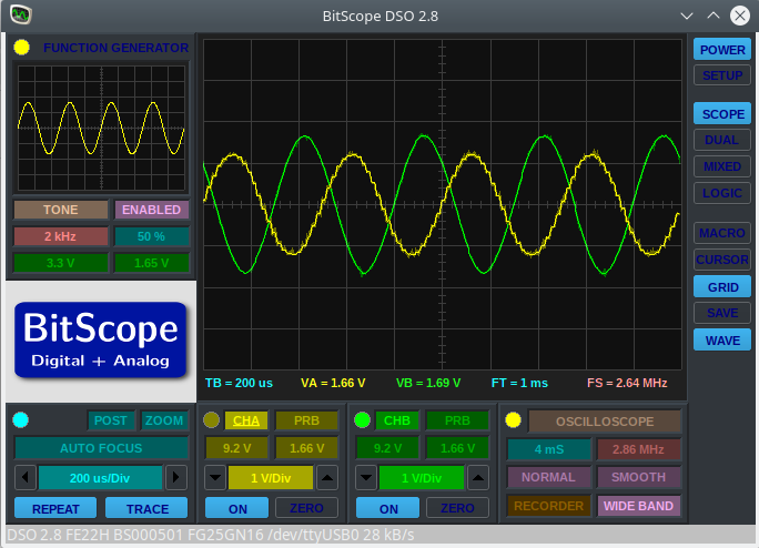
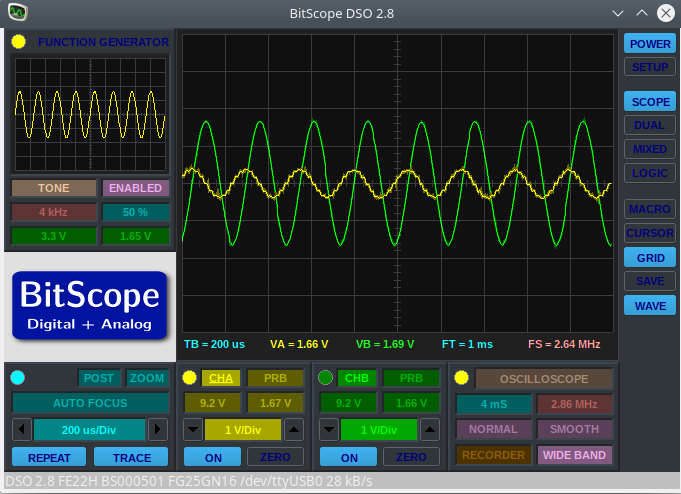
The SPI waveforms for the read ID transaction are shown below. Data reads and writes were successful at 5.33MHz. In a later post I will try bumping this speed up a bit.