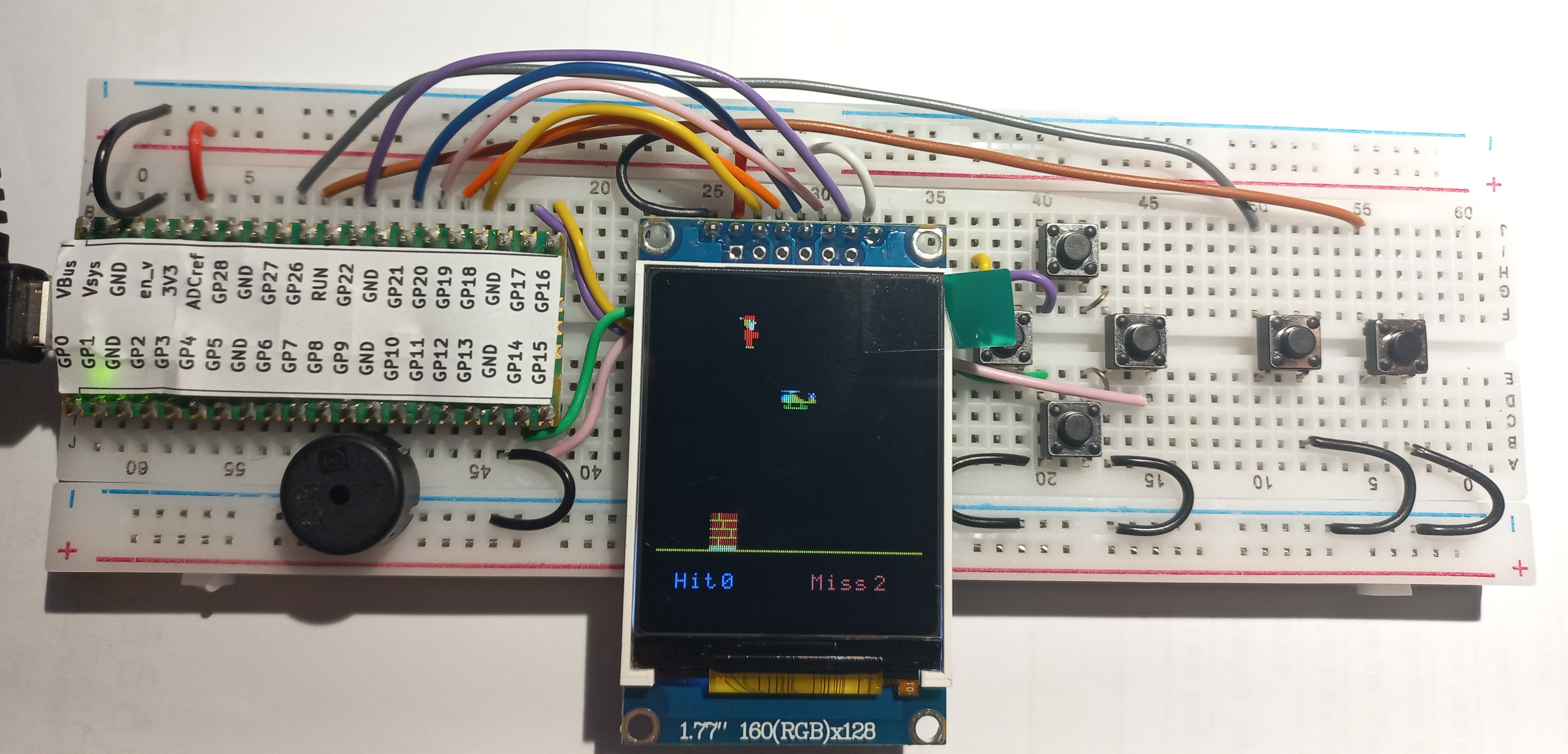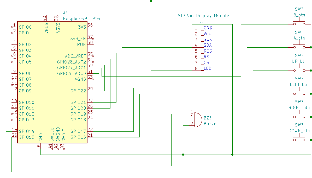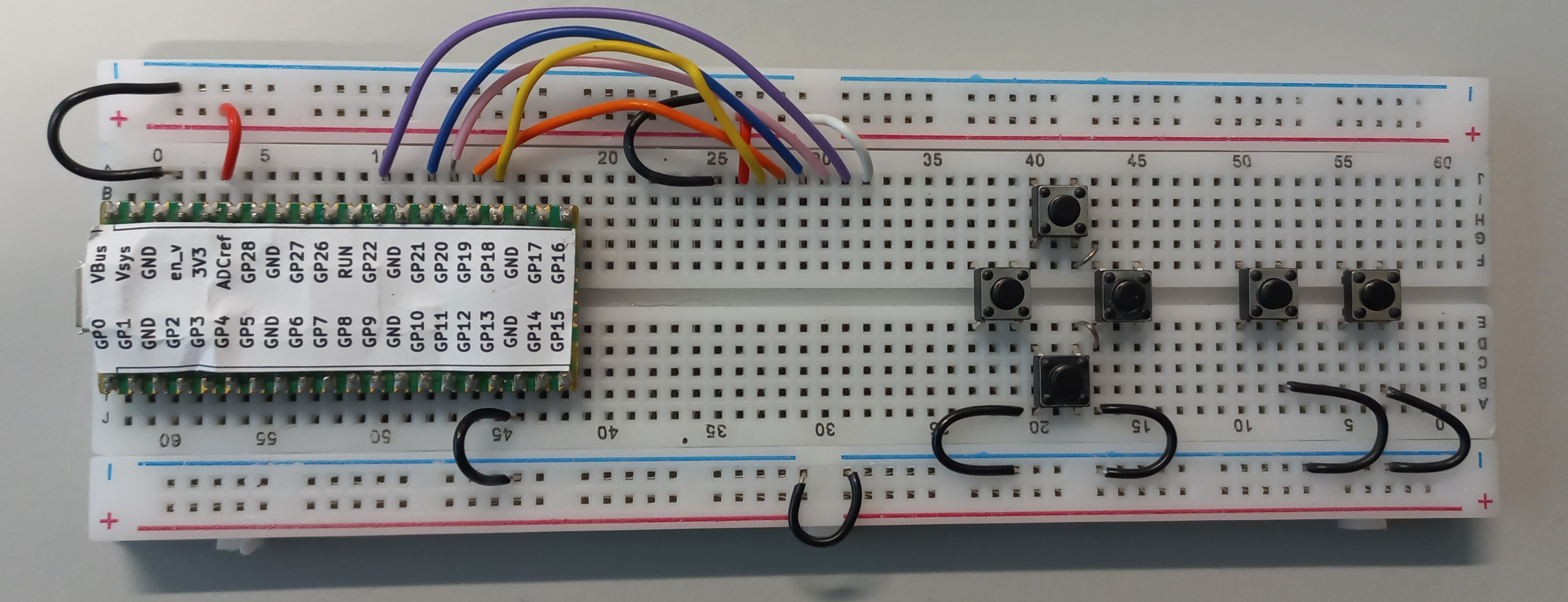
Note on board co-ordinates:
There are two sets of co-ordinates shown on the board. We will be using the ones that are the “right way up” i.e. the ones shown on the left side of the image. Some of the images can be a little misleading because of the angle the photos were taken. This is particularly true for the red and black wires at the top left of the image. The red wire connects to 3V3 to any hole just above the red line. The black wire connects GND to any hole just below the blue wire.
Display wiring:
White : Column 32, Row A to any hole just above the red line (keep it left of Column 30)
Purple : Column 31, Row A to GP22
Pink : Column 30, Row A to GP20
Blue : Column 29, Row A to GP21
Orange : Column 28, Row A to GP19
Yellow : Column 27, Row A to GP18
Red : Column 26, Row A to any hole just above the red line (3.3V)
Black : Column 25, Row A to any hole just below the blue line (0V)
Buttons: Place as shown.
Black wires (0V) These are used connect GND (0V) signals together.
Link wires between buttons
Column 42, Row E to Column 43, Row D
Column 42, Row F to Column 43, Row G

Button wiring. Try to get at least some of the button wires into the channel between the top and bottom halves of the breadboard.
Brown : GP26 to Column 55, Row A
Grey : GP27 to Column 50, Row A

Purple : GP17 to Column 14, Row E
Buzzer: GP9 to any hole just below the blue line
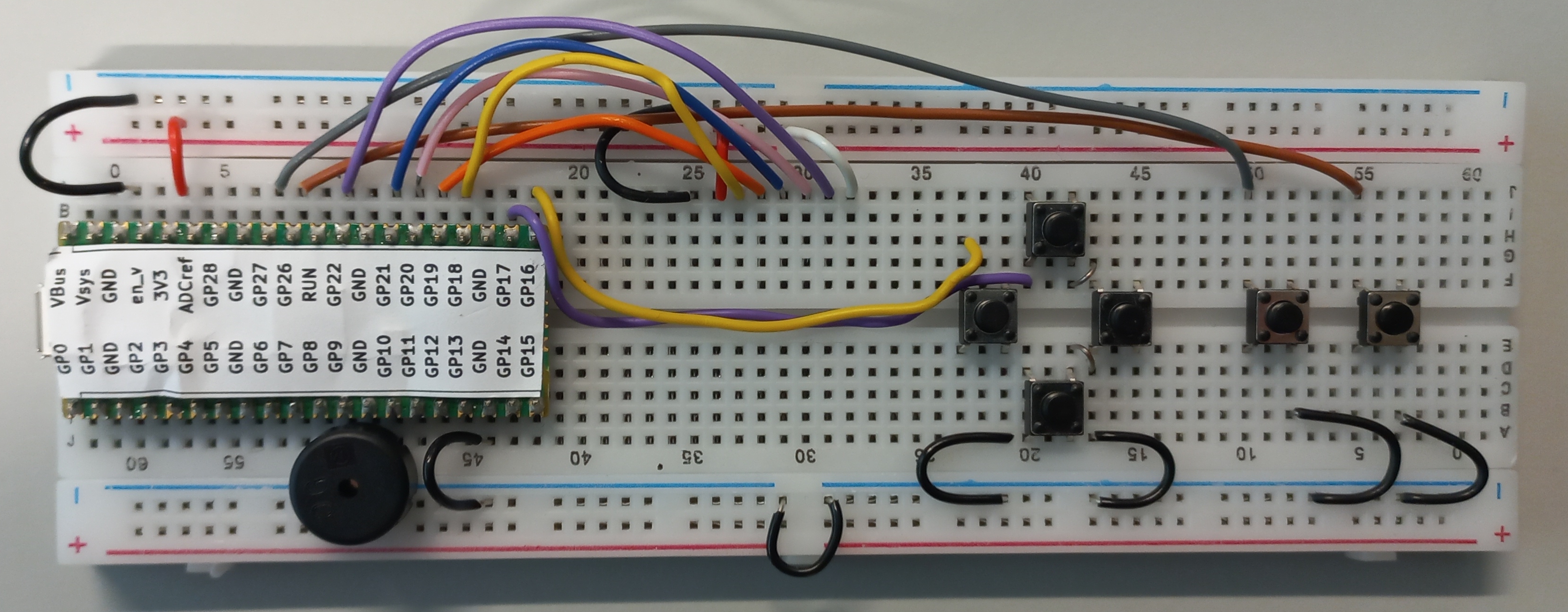
Yellow: GP16 to Column 36, Row C

White : GP15 to Column 45, Row C
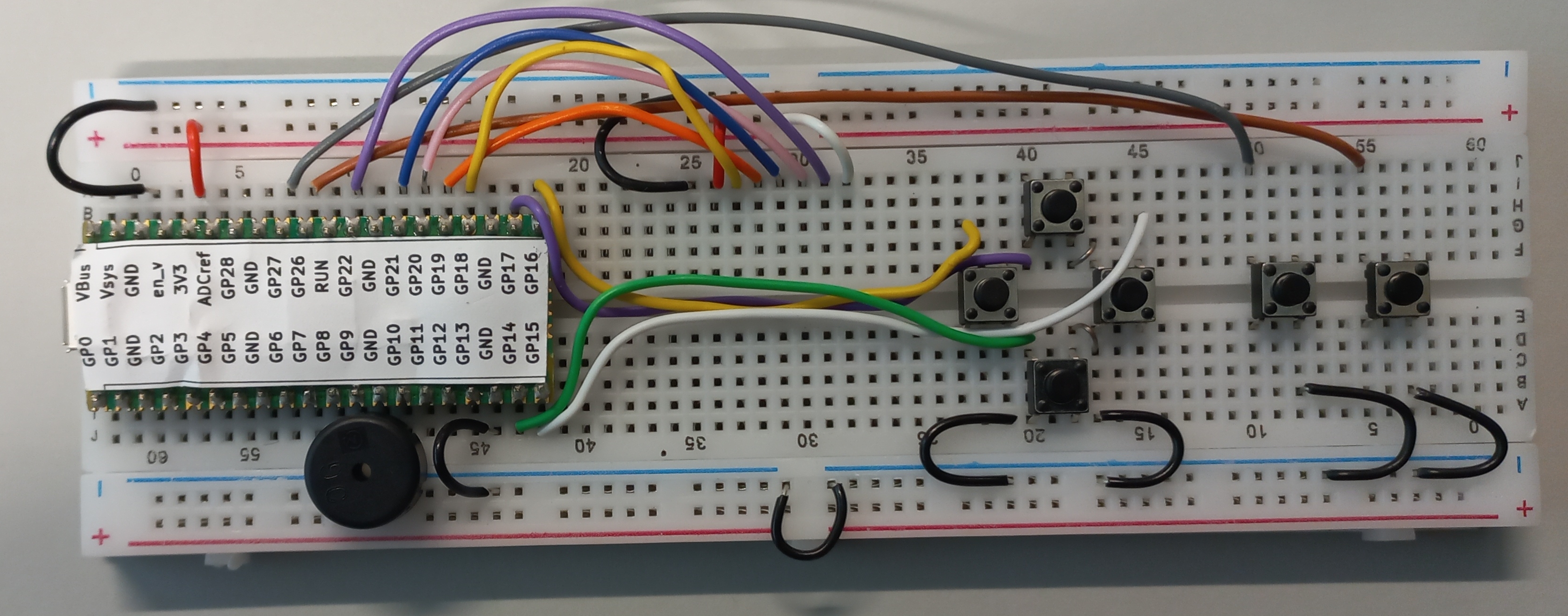
Green: GP14 to Column 40, Row F

WARNING : ASK FOR ASSISTANCE WITH THIS. DISPLAY ARE FRAGILE!
Fit the display as shown in the row of holes just below the display wires. The rightmost pin of the display should line up with the small white wire.