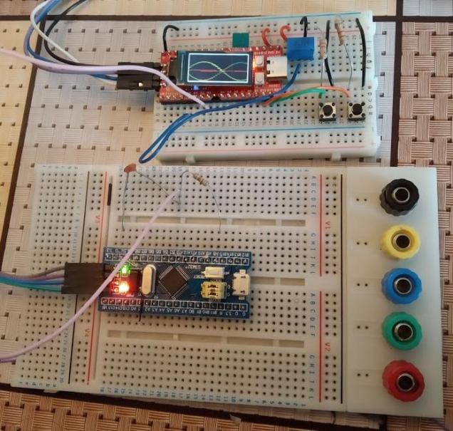
The Longan-Nano comes with a nice little display that opens up lots of possibilities. One of these is an oscilloscope. The GD32VF103 on the board has a pair of fast ADC’c that supposedly work up to 1MHz. The approach I took didn’t quite achieve this so I had to settle for 500kHz instead – good enough for a demo.
The code makes use of Timer 2 to pace (trigger) ADC conversions on two channels (one on each ADC) which are labelled A0 and A3 on the ‘nano.
The picture above shows the display when two inputs are used: A steady DC value from a potentiometer and a sine-wave generated by a blue-pill board doing some fast PWM (See this post).
The picture of the display is showing “ghosting” because of the slow shutter speed of the camera.
Two buttons are fitted to the board to allow the user increase and decrease the sample rate which stretches and compresses the waveform on the screen.
This is not meant to be an actually useful instrument – it’s just a learning exercise for this device.
Code is over on github.
GD32VF103CBT6
Measuring GD32VF103 Interrupt response time
Following on from the previous article that talked about the ECLIC in the GD32VF103 RISC-V microcontroller I decided to measure its interrupt response. The example works like this: Configure a port pin to generate an interrupt when it goes through a high-low transition. The interrupt handler then drives the pin back high again.
The main body of this example consists of a loop which drives the pin low thus triggering an interrupt. The interrupt handler sends it high again. This is done in a loop which incorporates a small delay to facilitate measurement. The GPIO pin in question is Port C bit 13 which happens to control the red LED on the Sipeed Longan Nano. The results are shown in the figure below.
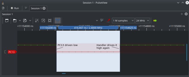
As can be seen, it takes 416.667ns to drive the pin high again. This corresponds to 45 clock cycles at 108Mhz which is the time it takes to save the CPU registers, determine the cause of the interrupt, jump to the handler and perform a standard function entry prologue (set up stack etc). Not too shabby 🙂
Interrupts and the GD32VF103
Interrupt handling is a core part of embedded systems and different architectures have different ways of dealing with it. The RISC-V Bumblebee core in the GD32VF103 uses an interrupt controller called the Enhanced Core-Local Interrupt Controller (ECLIC). All interrupts (internal and external) are handled by the ECLIC. The ECLIC handles prioritization and level/edge triggering of interrupts.The documentation on the ECLIC is pretty poor at the moment. The Bumblebee core datasheet is formatted very badly (fonts all over the place, broken diagrams etc) and it was only by combining this with the assembler provided in the GD32VF103 that I began to get a clearer picture of what is going on.
The ECLIC has two modes of dealing with interrupts : vectored and non-vectored. Vectored interrupt handling is similar to other MCU’s such as the ARM, MSP430 etc. The CPU receives interrupt request ‘N’ and finds the interrupt handler by looking up entry ‘N’ in the interrupt vector table. Saving of registers (context saving) is left to the writer of the interrupt handler and on exit the handler often must execute a return from interrupt instruction (though not for all architectures).
Non-Vectored interrupt handling is quite different. All interrupt requests cause the same interrupt handler code to be executed initially. This code saves the CPU registers, finds out which interrupt happened and calls the handler pointed to by the appropriate interrupt vector table entry. This happens using a standard subroutine/function call instruction. The handler deals with the interrupt and executes a normal function return instruction. The registers are then restored and a return from interrupt instruction is executed.
The advantage of this approach is that the code to preserve/restore the registers is done (safely) and only needs to occur once in memory. Also, the interrupt handlers can be written in C or C++ without the need to tag on unusual attributes like “interrupt” etc. The potential disadvantage is that maybe the handling of interrupts is a little slower than it might have been using the vectored approach because you end up saving and restoring all CPU registers – whether you use them or not.
Excerpt from ~/.platformio/packages/framework-gd32vf103-sdk/RISCV/env_Eclipse/entry.S
.weak irq_entry
irq_entry: // -------------> This label will be set to MTVT2 register
  // Allocate the stack space


  SAVE_CONTEXT// Save 16 regs

  //------This special CSR read operation, which is actually use mcause as operand to directly store it to memory
  csrrwi  x0, CSR_PUSHMCAUSE, 17
  //------This special CSR read operation, which is actually use mepc as operand to directly store it to memory
  csrrwi  x0, CSR_PUSHMEPC, 18
  //------This special CSR read operation, which is actually use Msubm as operand to directly store it to memory
  csrrwi  x0, CSR_PUSHMSUBM, 19

// ****************** THIS IS WHERE THE JUMP TO THE INTERRUPT HANDLER FUNCTION HAPPENS! **************

service_loop:
  //------This special CSR read/write operation, which is actually Claim the CLIC to find its pending highest
  // ID, if the ID is not 0, then automatically enable the mstatus.MIE, and jump to its vector-entry-label, and
  // update the link register
  csrrw ra, CSR_JALMNXTI, ra

  //RESTORE_CONTEXT_EXCPT_X5

  #---- Critical section with interrupts disabled -----------------------
  DISABLE_MIE # Disable interrupts

  LOAD x5,  19*REGBYTES(sp)
  csrw CSR_MSUBM, x5
  LOAD x5,  18*REGBYTES(sp)
  csrw CSR_MEPC, x5
  LOAD x5,  17*REGBYTES(sp)
  csrw CSR_MCAUSE, x5


  RESTORE_CONTEXT


  // Return to regular code
  mret
The comments just before the instruction csrrw ra, CSR_JALMNXTI, ra are a little obscure but their sense is clear enough: If there is a pending interrupt the ECLIC will execute a call to its interrupt handler and will update the Link Register so that when the handler executes a return from subroutine instruction control will return to the next line in the irq_entry.
The macros SAVE_CONTEXT, RESTORE_CONTEXT are defined elsewhere in the startup source code. The constant CSR_JALMNXTI evalautes to 0x7ed – a register number in the ECLIC. According to the Bumblebee core data sheet this register is
“The custom register is used to enable the ECLIC interrupt. The read operation of this register can process the next interrupt and return the entry address of the next interrupt handler. Jump to this address.”.
This is the mechanism by which the developer supplied interrupt handler is called.
How does the irq_entry code get called in the first place? Looking at the code for .platformio/packages/framework-gd32vf103-sdk/RISCV/env_Eclipse/start.S we find the following code that executes during boot:
_start:

        csrc CSR_MSTATUS, MSTATUS_MIE
        /* Jump to logical address first to ensure correct operation of RAM region  */
    la          a0,     _start
    li          a1,     1
        slli    a1,     a1, 29
    bleu        a1, a0, _start0800
    srli        a1,     a1, 2
    bleu        a1, a0, _start0800
    la          a0,     _start0800
    add         a0, a0, a1
        jr      a0

_start0800:

    /* Set the the NMI base to share with mtvec by setting CSR_MMISC_CTL */
    li t0, 0x200
    csrs CSR_MMISC_CTL, t0

        /* Intial the mtvt*/
    la t0, vector_base
    csrw CSR_MTVT, t0

        /* Intial the mtvt2 and enable it*/
    la t0, irq_entry
    csrw CSR_MTVT2, t0
    csrs CSR_MTVT2, 0x1
Note the instructions la t0, irq_entry , csrw CSR_MTVT2, t0 . These tell the ECLIC where to find the irq_entry code. The Bumblebee core reference manual defines this register CSR_MTV2 (0x7ec) as
“Custom registers are used to set non-vector interrupt handling Mode interrupt entry address” .
So, there we have it. The picture below shows my rough understanding of the process.

I have written up two more demo programs: One which uses the internal clock cycle timer interrupt (mtimecmp) (Systick interrupt), the other uses Timer 6 as an external source of timer interrupts (TimerIRQ). Code is available over on Github
Longan-nano RISC-V and PlatformIO
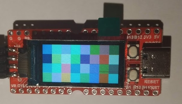
The Longan-nano board shown above includes a microcontroller with a RISC-V core. The chip seems to be very similar to the STM32F103C8T6 with the exception that the ARM-Cortex M3 core has been swapped out for a RISC-V Bumblebee core called the GD32VF103CBT6. This little development kit has an Arduino nano form factor and also sports a 160×80 full colour display, an RGB LED and a micro SD-card socket. This particular one came from Seeed Studio at a cost of $4.90 + shipping.
There are two ways of programming this chip: You can use a JTAG debugger (various kinds supported) or you can put the chip into DFU (Device Firmware Update) mode by holding the Reset and Boot button down, releasing the Reset button first. This allows you to program the board using a simple USB-Serial converter. I’ve gone with this initially but will definitely be exploring the details of the RISC-V core with a proper debugger shortly.
Developing code
The documentation for this chip pushes you towards using PlatformIO for development. This is an extension for Visual Studio Code – another first for me. You first install VSCode and then add in the PlatformIO extension (I just followed the online guide and it all just worked 🙂 )
There is good support for the GD32VF103CBT6 within PlatformIO and so there is no problem with setting up environment variables, directories and so on. I chose to develop in C++ which caused me a slight problem with the gd32vf103.h header file. This is intended for use with C projects and includes a definition the bool type. This causes a problem for C++ as it already has such a type. If you edit gd32vf103.h as follows you can fix this (around line 180 look for the enum declaration called bool)
#ifndef __cplusplus
typedef enum {FALSE = 0, TRUE = !FALSE} bool;
#endif
One more thing: when you include this file in your C++ files be sure to surround the include statement with “extern C” as shown below:
extern "C" {
#include "gd32vf103.h"
}
If you don’t do this you run into all sorts of problems with C++ decorated names.
And along came a gotcha
I have to admit that I have been a little lazy when it comes to function return values over the years. Let’s say you write an I/O function that may, in some future design, return an error code – as the project is only starting however you have not written that code yet.
So, your code might look like this:
int test()
{
    int X;
    X = 1;
    /* etc */
}
Note the missing return statement – after all, you haven’t written that code yet. Well, this runs fine on ARM Cortex MCU’s I’ve used, and, also on x86. On RISC-V/GCC9.2 this crashes your program. I spent a while scratching my head over this one. The C++ standard apparently states that behavior in this example is “undefined”. So, be warned: If you state that you are going to return a value then do!
Demo code
I’ve started a repository on github with some examples (multi-colour blinky and a graphics demo for now). You can view it here
