Breadboard Games 2021

Given the pandemic restrictions this year Breadboard Games will be delivered remotely. Participants will each receive a kit and work with a parent to assemble the gaming console. Remote support will be provided via video.

Instructions

This is a breadboard. It allows us to connect electronic components together by pushing them into the holes. In the centre region all the holes in column 1 are connected together inside the board apart from the gap in the middle. Columns 2 to 30 work similarly. You can see more about breadboards at this location


In the outer, between the blue and red lines, connections run horizontally within the breadboard. We usually use these areas to connect power supplies for our electronic components.

Lets begin by putting the black wires into the board as shown above. The top row of holes next to the blue line will be used to distribute the 0V connections for our circuit (the negative terminal on our battery). The connections are expressed in Row,Column terms as follows:

j6 to 0V (approximately directly above just next to the blue line)
j9 to 0V
a1 to 0V
a24 to 0V
a27 to 0V
a30 to 0V

A diode only allows electricity to flow in one direction. We include one here to protect our game in case somebody connects the battery pack in backwards. The diode has two wires : Cathode and Anode.

We want electrical current to flow into hole j7 so put the cathode in there and the anode just above the red line as shown.

Connect the red wire between j5 and j10.
The other component is a resistor. Resistors control the flow of electrical current. We are using this one to limit the brightness of our display so that the batteries last longer. The resistor connections between f9 and f16. Note the way the resistor sits in the valley between both halves of the breadboard.

The screen in our game is a “touch-screen”, just like a phone. We have to add a couple of wires to support this. The yellow wire goes from e10 to f13. The blue wire goes from d9 to f23

The purple wires are used to connect the buttons to the little computer in our game. They are connected as follows:
a3 to a18
a19 to a28
a20 to a25

The buttons go in next. Each button has two “pins” that are connected together electrically when you push down. The left button we will call simply “Left”, the rightmost button we will call “Right” and the middle buttonw we will call “Fire”. The connections are as follows:
Left: c1 and c3
Fire: c25 and c27
Right : c28 and c30

We are nearly done. The computer board that controls our game needs to go in next. Before you put it in be sure that all of the previous connections are correct. It is difficult to remove the computer boards if you need to correct any errors. Push the board firmly into the breadboard with the pin marked “3.3” (top left) in hole g5.

And now for the screen. Be very careful putting this in. It goes in row i. The rightmost pin of the display goes into hole i24. Push down on the pins only, not the glass. The glass will crack if you push on it.

Our game makes sounds. The buzzer is connected between a17 and 0V (just below the blue line). The longer leg of the buzzer (labelled +) goes in to a17.

The battery pack plugs into the board as shown above. Note the red wire is closest to the red line on the breadboard. The on/off switch should be just behind the display on the right hand side. If you like you can stick the breadboard to the battery pack using the adhesive backing on the breadboard. If you decide to do this be very careful as the adhesive backing is very strong.

All software used in this game is available on my github repository

Fast PWM on the STM32F103 Bluepill

I needed a signal source for another project I’m working on so I set about building a signal generator of sorts using a “Bluepill” board. The STM32F103 on these boards does not have a Digital to Analogue Converter but it does have a very capable timer which can be used to generate waveforms.
STM32F103_TIM1_DMA_PWM

The timer (TIM1) is shown in the diagram above. In the mode that it is configured for this project it works as follows:
The CNT register counts up to the value in ARR
When CNT = ARR the upper digital comparator outputs a pulse which is used to reset CNT to 0 and to set the PWM output signal high (via the S-R Flip-Flop).
When CNT is equal to the value in CCR1, the lower digital comparator outputs a pulse which resets the PWM output low. ARR therefore controls the output frequency while CCR1 controls the output duty.
(CNT = count, ARR = auto-reload register, CCR1 = Counter-Compare Register 1)

I’m interested in producing audio range signals so up to about 20kHz. An trade-off between switching frequency, resolution, and output filtering arises here. First of all, I want to use a simple RC filter on the output to remove the high frequency switching. This means that the switching frequency has to be a lot higher than the target output signal i.e. much greater than 20kHz. But how much higher? The clock in the STM32F103 runs at 72MHz so this places an upper limit on things. Lets say we go for a switching frequency of 12MHz. This means that the counter will count from zero to five and then back up to zero again (6 states in total). This means that our PWM waveform generation system is only able to produce 6 different outputs (between 2 and 3 bits of resolution) which is pretty poor. I wanted a lot more resolution than that so after playing with the numbers I arrived at the following. Let ARR = 255 (8 bits of resolution). This gives a switching frequency of 280500Hz which is certainly not audible and is pretty easy to filter with passive components.
In order to produce a sine-wave output the CCR1 value needs to be varied sinusoidally. This could be done by generating an interrupt for each PWM cycle and loading values from a look-up table into CCR1. This places a reasonably high load on the CPU however given the high switching frequency. Another option is to use DMA which can transfer values from the lookup-table directly into CCR1. After all the values of the table have been used up, the DMA controller can then generate an interrupt allowing the program to perhaps modify the output signal if necessary. The interrupt rate is a lot lower with this approach and the CPU is free to do other tasks.
stm32f103_280kHz_PWM_logic_out
The figure above shows a logic analyzer view of the outputs. The upper signal is a fixed duty signal from CCR2 (another PWM output channel). The middle signal is the sinusoidal PWM output. The lower signal is a digital output that is toggled at the end of each DMA transfer (every millisecond).

After filtering the output looks like this:
stm32f103_280kHz_PWM

The upper trace is the PWM output after it has been passed through an RC filter with a cutoff of 20kHz. As expected the switching frequency (which is most pronounced around zero-crossings of the sinewave) is attenuated to about 1 tenth of its original size. The lower trace shows the unfiltered output.

The next step is to produce a variable frequency and voltage output – perhaps even two channels. Code is available over on github
Incidentally, the particular board used here is one with 128kB of flash (earlier ones I used had only 64kB).

A measurement of the performance of Rust vs C.

This post follows on from my previous one which was an opening foray into the world of Rust. Following a comment I received I decided I would look at the relative performance of Rust and C for the trivial example of blinky running as fast as the CPU can do it (using the default reset clock speed). This involved modifying the C and Rust code.
The modified main.c
The modified code for main.c is shown below. The main differences between this and the version from my previous post are:
#defines used to define the addresses of the I/O registers. This means that the handling of pointer indirection happens at compile time – not run time. Also, it means that RAM is not used to represent the pointers at run-time.
The BSR and BRR (bit-set and bit reset registers) are used for setting and clearing bit 13. This produces smaller and faster code as there is no software bitwise AND/OR involved at run-time.
Two build changes:
optimization is turned up to level 2 by passing the -O2 argument to arm-none-eabi-gcc
debugging information is removed (building for release)

/* User LED for the Blue pill is on PC13 */
#include  // This header includes data type definitions such as uint32_t etc.
#define rcc_apb2enr (  (volatile uint32_t *) 0x40021018  )
#define gpioc_crh  (  (volatile uint32_t *) 0x40011004  )
#define gpioc_odr (  (volatile uint32_t *) 0x4001100c  )
#define gpioc_bsr (  (volatile uint32_t *) 0x40011010  )
#define gpioc_brr (  (volatile uint32_t *) 0x40011014  )


// The main function body follows 
int main() {
    // Do I/O configuration
    // Turn on GPIO C
    *rcc_apb2enr |= (1 << 4); // set bit 4
    // Configure PC13 as an output
    *gpioc_crh |= (1 << 20); // set bit 20
    *gpioc_crh &= ~((1 << 23) | (1 << 22) | (1 << 21)); // clear bits 21,22,23
    while(1) // do this forever
    {
        *gpioc_bsr = (1 << 13); // set bit 13       
         *gpioc_brr = (1 << 13); // clear bit 13     
    }
}
// The reset interrupt handler
void reset_handler() {
    main(); // call on main 
    while(1); // if main exits then loop here until next reset. 
}

// Build the interrupt vector table
const void * Vectors[] __attribute__((section(".vector_table"))) ={
	reset_handler
};

This code is built and gdb reports it's load size as 76 bytes when loaded onto the STM32F103. Executing the code we see the port pin behave as follows:

rust_blink_speed
I’m not clear on why there is a variation of cycle length every other cycle – maybe its as a result of the sampling on my cheap logic analyzer but the important point here is that the waveform is exactly the same for both C and Rust versions of this program so there is no performance hit in tight loops such as this.

The Rust version
The Rust version of the program is shown below. This is different to the version in my previous post as it uses the stm32f1 crate. The example is taken from a Jonathan Klimt’s blog over here. There’s quite a lot going on under the surface in this crate but crucially this all seems to happen at compile time because the output code is just as efficient as the C code from a speed perspective although it is a good deal bigger : 542 bytes vs C’s 76. Why the difference? There are several reasons but one big chunk is accounted for by the fact that the Rust version has a fully populated interrupt vector table which takes up 304 bytes. The C-version only includes the initial stack pointer and the Reset vector : a total of 8 bytes.

// std and main are not available for bare metal software
#![no_std]
#![no_main]

extern crate stm32f1;
extern crate panic_halt;
extern crate cortex_m_rt;

use cortex_m_rt::entry;
use stm32f1::stm32f103;

// use `main` as the entry point of this application
#[entry]
fn main() -> ! {
    // get handles to the hardware
    let peripherals = stm32f103::Peripherals::take().unwrap();
    let gpioc = &peripherals.GPIOC;
    let rcc = &peripherals.RCC;   

    // enable the GPIO clock for IO port C
    rcc.apb2enr.write(|w| w.iopcen().set_bit());
    gpioc.crh.write(|w| unsafe{
        w.mode13().bits(0b11);
        w.cnf13().bits(0b00)
    });

    loop{
        gpioc.bsrr.write(|w| w.bs13().set_bit());        
        gpioc.brr.write(|w| w.br13().set_bit());                
    }
}

The blinky loops in assembler
The version produced by the C code is shown below. r1 and r2 have been previously set up to point at the BSR and BRR registers; while r3 contains the mask value (1 << 13).

   0x08000034 :    str     r3, [r1, #0]
   0x08000036 :    str     r3, [r2, #0]
   0x08000038 :    b.n     0x8000034 

The version produced by the Rust code is below. In this case, r0 is set to point at the data structure that manages Port C and the offsets used in the store instructions are used to select the BSR and BRR registers. Register r1 has been preset to the mask value (1 << 13).

   0x0800017a :    str     r1, [r0, #12]
   0x0800017c :    str     r1, [r0, #16]
   0x0800017e :    b.n     0x800017a 

Final thoughts
Rust is considered to be a safer language to use than C. This benefit must come at some cost however. I’ve seen here that the cost is not in execution speed so where is it? Well, the C version is completely built in 168ms while the Rust version takes over 2 minutes – note this is a “once-off” cost in a way; incremental builds are nearly as quick as the C version. A full rebuild only happens if you build after a “cargo clean” command or if you modify the Cargo.toml file (which changes the build options).
Does this encourage me to pursue Rust a little more – definitely yes and with a more complex project that might reveal the greater safety of Rust.

Rust and C side-by-side on the STM32F103C8T6 (“Blue pill”) board

rustybluepill2
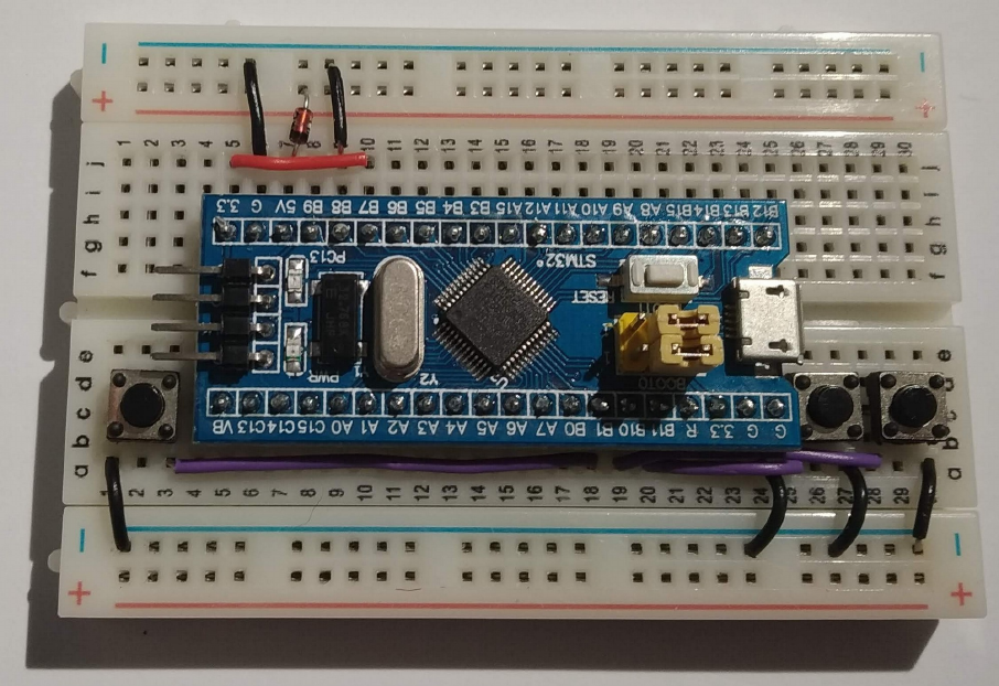
For most people, the first program they write for an MCU is “blinky”. This post explores blinky in C and Rust for the STM32F103C8T6 Blue pill board. This board has a built-in LED on port C bit 13. Programs are downloaded via an STLink-V2 SWD debug interface clone.

What does the program do?

When you power on an STM32F103 it looks to the lower addresses in FLASH memory to figure out what to do. The first entry (32 bit) should contain the value for the initial stack pointer. This is typically set to the top of RAM. The next entry is the address of the code that handles reset : the reset_handler.
Typically, the job of the reset handler is to initialize global and static variables and maybe perform some clock initialization. When this is done it then calls on the “main” function although this is not essential : you can write all your code in the reset handler. I prefer to use the main function.
In order to make the LED blink the main function must configure the appropriate GPIO pin as an output (Port C, bit 13). Having done this, the program enters an endless loop which does the following:
Set port C bit 13 high (turning on the LED)
Wait for a while (so the user can see the LED change)
Set port C bit 13 low (turning off the LED)
Wait for a while (so the user can see the LED change)
And that’s it. Now lets look at the C and Rust ways of doing this. Note: these are very much minimal programs that seek to bridge the gap between the higher level languages and the hardware. They don’t necessarily represent a recommended programming style for complex systems.

Blinky in C : memory layout
memory_layout

The figure above shows how the linker script file (linker_script.ld) lays out the memory image output by the linker. Flash memory starts at address 0x08000000. The initial stack pointer value is set by the line:

          LONG(ORIGIN(RAM) + LENGTH(RAM));

which evaluates to 0x20005000.
The interrupt vector table is then placed immediately after this – the reset vector being the first and only entry in this case. The text section contains code, rodata contains constants and so on. The ARM.exidx section contains data that can be used during debugging to perform a stack backtrace. The last section is not really relevant to this example but is included for completeness. This is used to help initialize global and static data.

Blinky in C : code

/* User LED for the Blue pill is on PC13 */
#include  // This header includes data type definitions such as uint32_t etc.

// Simple software delay.  The larger dly is the longer it takes to count to zero.
void delay(uint32_t dly) {
    while(dly--);
}
// GPIO configuration
void config_pins() {
    // Make pointers to the relevant registers
    volatile uint32_t * rcc_apb2enr = (  (volatile uint32_t *) 0x40021018  );
    volatile uint32_t * gpioc_crh = (  (volatile uint32_t *) 0x40011004  );
    
    // Turn on GPIO C
    *rcc_apb2enr |= (1 << 4); // set bit 4
    // Configure PC13 as an output
    *gpioc_crh |= (1 << 20); // set bit 20
    *gpioc_crh &= ~((1 << 23) | (1 << 22) | (1 << 21)); // clear bits 21,22,23
}
void led_on() {
    // Make a pointer to the output data register for port C
    volatile uint32_t * gpioc_odr = (  (volatile uint32_t *) 0x4001100c  );
    *gpioc_odr |= (1 << 13); // set bit 13
}

void led_off() {
    // Make a pointer to the output data register for port C
    volatile uint32_t * gpioc_odr = (  (volatile uint32_t *) 0x4001100c  );
    *gpioc_odr &= ~(1 << 13); // clear bit 13
}
// The main function body follows 
int main() {
    // Do I/O configuratoin
    config_pins(); 
    while(1) // do this forever
    {
        led_on();
        delay(100000);
        led_off();
        delay(100000);
    }
}
// The reset interrupt handler
void reset_handler() {
    main(); // call on main 
    while(1); // if main exits then loop here until next reset. 
}

// Build the interrupt vector table
const void * Vectors[] __attribute__((section(".vector_table"))) ={
	reset_handler
};

Let's start at the bottom of the code: Here you can see the interrupt vector table being defined. It begins with:

    const void * Vectors[] __attribute__((section(".vector_table"))) ={

What does this mean:
Vectors is a an array of constant pointers to undefined types. It is given the linker section attribute ".vector_table" which places it at the appropriate place in the program memory image. There is just one element in this array: reset_handler which represents the address of that function. So, when reset or power up happens, the first code to be executed will be at the address “reset_handler”. In this example, the reset_handler code simply calls on main. If by some chance the main function exits, reset_handler then enters an empty endless loop.
The main function calls on lower level functions : config_pins, led_on, delay and led_off.

The job of config_pins is to set up GPIO Port C, bit 13 as an output. Note the way pointers to the hardware registers are created. This mechanism is less than ideal because the pointer takes up valuable RAM. It is more usual to use #define macros for these pointers instead but this approach is taken here so that the C code lines up with the Rust code more closely.
The functions led_on, led_off behave in a similar way. The delay function implements a simple software delay loop. The program is built with the following command line (this is in a “batch” file in the github repository called build.bat – this batch file extension is chosen so that it can be directly executed on Windows as well as Linux)

    arm-none-eabi-gcc -static -mthumb -g -mcpu=cortex-m3 *.c -T linker_script.ld -o main.elf -nostartfiles 

This invokes the arm gcc compliler, performs static linking (no dll’s), generates “thumb” code, with debugging information for the arm-cortex-m3 core. All C files in the current directory are included. The linker is instructed to use this particular linker script, the output program will be called main.elf and the linker is instructed not to include any default initialization code (the reset_handler function does this). You must have arm-none-eabi-gcc installed on your system and reachable via the PATH environment variable.

Blinky in Rust
Rust uses a linker file just like C – in fact it is identical apart from a couple of minor points:
1) It is called memory.x (which is in line with other examples on the Internet)
2) It doesn’t contain the section relating to the initialization of global and static variables.

While the C version of the program sits entirely in one directory, the Rust version is distributed across a number of sub-directories. This is because the Rust build tool Cargo is used. The directory tree is as follows:
cargo_directories

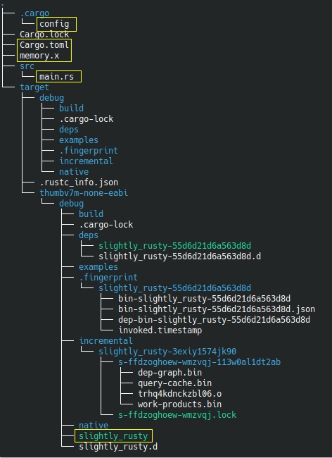
This is obviously WAY more complex however you really only have to concern yourself with the highlighted files.

The config file in the “.cargo” directory contains the following:

[target.thumbv7m-none-eabi]
rustflags = ["-C", "link-arg=memory.x"]

[build]
target = "thumbv7m-none-eabi"

This tells the rust compiler the target architecture : thumbv7m (Cortex m3), none (no operating system), eabi : defines the function calling convention, the way data is organized in memory and the object file format as embedded application binary interface. The rustflags setting causes the linker to use the linker script file memory.x when generating the program image.

The file Cargo.toml contains the following


[package]
name = "slightly_rusty"
version = "0.1.0"


[profile.release]
# enable debugging in release mode.
debug = true

This simply names the output executable file name, specifies the version number and causes debugging data to be included in the release version (can be handy while testing)

The memory.x linker script file has been discussed above.

The rust code for this project is included in main.rs. It is as follows:

#![no_main]
#![no_std]

use core::panic::PanicInfo;

fn delay(mut dly : u32) {
    
    while dly > 0
    {
        dly = dly -1;
    }
}
// GPIO configuration
fn config_pins() {
   unsafe {
        // Make pointers to the relevant registers
        let rcc_apb2enr  = 0x40021018 as *mut u32;
        let gpioc_crh    = 0x40011004 as *mut u32; 
                
        // Turn on GPIO C
        *rcc_apb2enr |= 1 << 4; // set bit 4
        // Configure PC13 as an output
        *gpioc_crh |= 1 << 20;  // set bit 20
        *gpioc_crh &= !((1<<23) | (1<<22) | (1 << 21)); // clear bits 21,22,23
    }
}

fn led_on() {
    unsafe {
        // Make a pointer to the output data register for port C
        let gpioc_odr  = 0x4001100C as *mut u32; 
        *gpioc_odr |= 1 << 13; // set bit 13
    }
}

fn led_off() {
    unsafe {
        // Make a pointer to the output data register for port C
        let gpioc_odr  = 0x4001100C as *mut u32; 
        *gpioc_odr &= !(1  ! = reset_handler;


// Rust requires a function to handle program panics - this one simply loops.  You 
// could perhaps write some code to output diagnostic information.
#[panic_handler]
fn panic(_panic: &PanicInfo) -> ! {
    loop {}
}

The code is pretty similar to the C code so let’s just look at some of the differences.
First of all, we see the #![no_main] macro. This tells rust that there is no default startup function. Without this the compiler generates an error saying “error: requires `start` lang_item” which presumably means it can’t find the
default entry point for this program – not a problem here as the reset_handler is the entry point.
The #![no_std] macro tells the rust ( and the linker) not to include the rust standard library as it is not implemented (at least not fully) for the thumbv7m-none-eabi target.

The next line: use core::panic::PanicInfo is a bit like a C-include. It includes the definition for the type “PanicInfo” which is needed by the panic handler at the end of the program. The rust functions that follow have obvious parallels with their C counterparts. The key differences are:
unsafe : this keyword suspends some of Rust’s compile time memory/type safety checking to allow raw pointers to be used.
(unsafe reference : https://doc.rust-lang.org/book/ch19-01-unsafe-rust.html). The data types are quite similar to those defined in stdint.h : uint32_t = u32 etc. Pointer behaviour is similar to C also. Consider this line from config_pins:

  let rcc_apb2enr  = 0x40021018 as *mut u32;

This declares rcc_apb2enr as a pointer to the address 0x40021018 which contains a changeable unsigned 32 bit integer. Pointer deferencing is just like C’s.
One additional difference: the bitwise NOT is an exclamation point (!) as opposed to C’s tilde (~)

To build the rust program the following command is executed from the same directory as the Cargo.toml file:

cargo build

Assuming all goes well the output executable is written to the file
target/thumbv7m-none-eabi/debug/slightly_rusty

Loading on to the chip
The output files main.elf and slightly_rusty are loaded in the same way on to the target hardware. Start an openocd session in one terminal from the top level directory (rust_vs_c) as follows
/usr/bin/openocd -f stm32f103_aliexpress.cfg
This is the default openocd (version 0.10.0) that comes with Ubuntu 19.04
Assuming your devices are plugged in ok you should see an output something like this:
Open On-Chip Debugger 0.10.0
Licensed under GNU GPL v2
For bug reports, read
http://openocd.org/doc/doxygen/bugs.html
Info : The selected transport took over low-level target control. The results might differ compared to plain JTAG/SWD
adapter speed: 1000 kHz
adapter_nsrst_delay: 100
none separate
none separate
Info : Unable to match requested speed 1000 kHz, using 950 kHz
Info : clock speed 950 kHz
Info : STLINK v2 JTAG v17 API v2 SWIM v4 VID 0x0483 PID 0x3748
Info : using stlink api v2
Info : Target voltage: 3.244914
Info : stm32f1x.cpu: hardware has 6 breakpoints, 4 watchpoints

In another window run arm-none-eabi-gdb and execute the following commands
target remote :3333
load c/main.elf
monitor reset

This loads the C version of the progam and you should see the blue pill’s onboard LED blink.
Execute the following commands to run the rust version:
load rust/target/thumbv7m-none-eabi/debug/slightly_rusty
monitor reset

Hopefully the LED starts blinking again.

Where to from here? There are crates (rust libraries) online that define the various peripherals for STM32F103 devices etc. I’ve begun looking at these and while they are great in that they convert the STM32 SVD files to Rust they are also quite big – leading to a quite large final executable. More investigations are needed as well as a project to drive it all along.
Code for these examples is over on github

Using Flash memory on the STM32F103

Some microcontrollers have a dedicated Non-Volatile-Memory (NVM) bank for storing calibration data, program settings and so on. The STM32F103C8T6 does not have NVM like this but it’s Flash program memory can be used with care for the same purpose. The Flash memory in this chip is divided into 1kiB sectors and there are 64 if them (0 to 63). The code to erase, write and read a sector is shown below:

int  writeSector(uint32_t Address,void * values, uint16_t size)
{              
    uint16_t *AddressPtr;
    uint16_t *valuePtr;
    AddressPtr = (uint16_t *)Address;
    valuePtr=(uint16_t *)values;
    size = size / 2;  // incoming value is expressed in bytes, not 16 bit words
    while(size) {        
        // unlock the flash 
        // Key 1 : 0x45670123
        // Key 2 : 0xCDEF89AB
        FLASH->KEYR = 0x45670123;
        FLASH->KEYR = 0xCDEF89AB;
        FLASH->CR &= ~BIT1; // ensure PER is low
        FLASH->CR |= BIT0;  // set the PG bit        
        *(AddressPtr) = *(valuePtr);
        while(FLASH->SR & BIT0); // wait while busy
        if (FLASH->SR & BIT2)
            return -1; // flash not erased to begin with
        if (FLASH->SR & BIT4)
            return -2; // write protect error
        AddressPtr++;
        valuePtr++;
        size--;
    }    
    return 0;    
}
void eraseSector(uint32_t SectorStartAddress)
{
    FLASH->KEYR = 0x45670123;
    FLASH->KEYR = 0xCDEF89AB;
    FLASH->CR &= ~BIT0;  // Ensure PG bit is low
    FLASH->CR |= BIT1; // set the PER bit
    FLASH->AR = SectorStartAddress;
    FLASH->CR |= BIT6; // set the start bit 
    while(FLASH->SR & BIT0); // wait while busy
}
void readSector(uint32_t SectorStartAddress, void * values, uint16_t size)
{
    uint16_t *AddressPtr;
    uint16_t *valuePtr;
    AddressPtr = (uint16_t *)SectorStartAddress;
    valuePtr=(uint16_t *)values;
    size = size/2; // incoming value is expressed in bytes, not 16 bit words
    while(size)
    {
        *((uint16_t *)valuePtr)=*((uint16_t *)AddressPtr);
        valuePtr++;
        AddressPtr++;
        size--;
    }
}

Writes and reads must be performed in 16 bit (half word) chunks so a little bit of type casting is necessary. The data type for the values to be read or written is void *. This allows a pointer to any type be passed without generating warnings. The sector start address must be on a 1k boundary. In this chip, Flash memory starts at 0x8000000 so sector start addresses can be 0x8000000, 0x8000400, 0x8000800, 0x8000c00, etc.
The data sheet states that the flash can withstand at least 10000 write cycles (does this include erases?). This seems like a pretty large amount but you would be surprised how quickly it can get used up. If your program requires to write to Flash memory regularly consider some wear leveling scheme.
Full code is available over here on GitHub

Another low cost dev kit from Aliexpress

stm32f103plusdebugger

STLink V2 clone debugger: $1.79
MCU breakout board : $1.68
Total : $3.47
Delivery time : 2 weeks

This development kit is based around the stm32f103C8T6MCU. This is a 72MHz Cortex M3 device with 64kB of flash memory and 20kB of RAM. The debugger is an ST-Link V2 clone which can be used to debug STM32 and STM8 devices. I used this with OpenOCD and needed to edit/creaqte the configuration files stm32f103_aliexpress.cfg and stm32f1x_64k.cfg (see below for contents of these files). Note: the register that tells OpenOCD the size of system flash incorrectly indicates 128kB so a value of 64kB is forced in the configuration file. The first test program was blinky of course but this time I decided NOT to write the device header file myself but instead make use of ST Microelectronics
System View Description file (SVD file) for this device. This can be downloaded from here: http://www.st.com/resource/en/svd/stm32f1_svd.zip. Contained in the zip file is STM32F103.svd : an XML description of the peripheral registers within the STM32F103. A separate utility called SVDConv.exe was used to convert this “svd” file to a header file suitable for use with GCC. The SVDConv utility was found in Keil’s ARM MDK (http://www2.keil.com/mdk5/). I’m working in Linux so the conversion command was:

wine ./SVDConv.exe STM32F103.svd --generate=header

This produced the header file STM32F103.h. The header uses structure definitions and pointers to structures to access peripherals and the registers within them. It also has a couple of dependencies include/core_cm3.h and include/system_ARMCM3.h. I started down the road of finding these only to realise that these too had further dependencies. Furthermore, they served to hide a lot of the startup code, interrupt vectors and so on that I like to keep an eye on. So, there are two choices: either remove the #include statements for the dependencies or create empty files with those names. I did the latter as it left the STM32F103.h file unchanged. An additional header file of my own (cortexm3.h) is needed to fix up a couple of missing symbols which are defined as shown below (other symbols are also defined):

#define __IO volatile
#define __IM volatile
#define __OM volatile

These symbols refer to Input/Output datatypes which should probably always be volatile – in short it works.
As an experiment, I tried using STM32Cube to generate code for a simple blinky project. First of all, I should say that it worked (more or less – I had to manually edit the output Makefile to point to the directory where arm-none-eabi-gcc was installed). This is probably a great tool for a company that is producing a range of products across different members of the ARM-Cortex family. From a teaching and learning perspective though the generated code is of limited use. It is littered with conditional compiles, helper functions that hide important details, and requires you place your code between various sets of comments. The generated code is also MUCH larger than the version below. In short it obscures the lower levels of the microcontroller that I’m interested in teaching. The approach I’ve taken here is to use the device’s SVD file for the peripherals and my own, simpler, device specific Cortex M3 cpu core file. I also used my own simplified initialization code to show exactly what goes on after reset.

Blinky

/* User LED is on PC13 */
#include <stdint.h>
#include "../include/cortexm3.h"
#include "../include/STM32F103.h"
void delay(uint32_t dly)
{
    while(dly--);
}
int main()
{
    // Turn on GPIO C
    RCC->APB2ENR |= BIT4;
    // Configure PC13 as an output
    GPIOC->CRH |= BIT20;
    GPIOC->CRH &= ~(BIT23 | BIT22 | BIT21);
    while(1)
    {
        GPIOC->ODR |= BIT13;
        delay(1000000);
        GPIOC->ODR &= ~BIT13;
        delay(1000000);
    }
}

This is built with a script file (or batch file) that executes the following commands:

arm-none-eabi-gcc -static -mthumb -g -mcpu=cortex-m3 *.c -T linker_script.ld -o main.elf -nostartfiles 
arm-none-eabi-objcopy -g -O binary main.elf main.bin

The second line of this is not necessary strictly speaking. I use the same script for mbed boards and the “bin” output format is useful there.

Running and debugging

I tried to write out all of the steps in this but decided that a video would be much better. Its over here:

Further examples

A number of other examples are to be found over here https://github.com/fduignan/stm32f103c8t6. These include Systick (at default 8MHz) speed, Systick at 72MHz and UART input/output.

Appendix: OpenOCD configuration files

stm32f103_aliexpress.cfg:

# FILE: stm32f103_aliexpress.cfg
# stm32f103 board and ST-Link v2 from Aliexpress
source [find interface/stlink-v2.cfg]
transport select hla_swd
set WORKAREASIZE 0x2000
source stm32f1x_64k.cfg
reset_config none

stm32f1x_64k.cfg

# FILE: stm32f1x_64k.cfg
# MODIFIED: script for stm32f1x family : forced Flash size to 64kB

#
# stm32 devices support both JTAG and SWD transports.
#
source [find target/swj-dp.tcl]
source [find mem_helper.tcl]

if { [info exists CHIPNAME] } {
   set _CHIPNAME $CHIPNAME
} else {
   set _CHIPNAME stm32f1x
}

set _ENDIAN little

# Work-area is a space in RAM used for flash programming
# By default use 4kB (as found on some STM32F100s)
if { [info exists WORKAREASIZE] } {
   set _WORKAREASIZE $WORKAREASIZE
} else {
   set _WORKAREASIZE 0x1000
}

#jtag scan chain
if { [info exists CPUTAPID] } {
   set _CPUTAPID $CPUTAPID
} else {+
   if { [using_jtag] } {
      # See STM Document RM0008 Section 26.6.3
      set _CPUTAPID 0x3ba00477
   } {
      # this is the SW-DP tap id not the jtag tap id
      set _CPUTAPID 0x1ba01477
   }
}

swj_newdap $_CHIPNAME cpu -irlen 4 -ircapture 0x1 -irmask 0xf -expected-id $_CPUTAPID

if { [info exists BSTAPID] } {
   # FIXME this never gets used to override defaults...
   set _BSTAPID $BSTAPID
} else {
  # See STM Document RM0008
  # Section 29.6.2
  # Low density devices, Rev A
  set _BSTAPID1 0x06412041
  # Medium density devices, Rev A
  set _BSTAPID2 0x06410041
  # Medium density devices, Rev B and Rev Z
  set _BSTAPID3 0x16410041
  set _BSTAPID4 0x06420041
  # High density devices, Rev A
  set _BSTAPID5 0x06414041
  # Connectivity line devices, Rev A and Rev Z
  set _BSTAPID6 0x06418041
  # XL line devices, Rev A
  set _BSTAPID7 0x06430041
  # VL line devices, Rev A and Z In medium-density and high-density value line devices
  set _BSTAPID8 0x06420041
  # VL line devices, Rev A
  set _BSTAPID9 0x06428041
}

if {[using_jtag]} {
 swj_newdap $_CHIPNAME bs -irlen 5 -expected-id $_BSTAPID1 \
	-expected-id $_BSTAPID2 -expected-id $_BSTAPID3 \
	-expected-id $_BSTAPID4 -expected-id $_BSTAPID5 \
	-expected-id $_BSTAPID6 -expected-id $_BSTAPID7 \
	-expected-id $_BSTAPID8 -expected-id $_BSTAPID9
}

set _TARGETNAME $_CHIPNAME.cpu
target create $_TARGETNAME cortex_m -endian $_ENDIAN -chain-position $_TARGETNAME

$_TARGETNAME configure -work-area-phys 0x20000000 -work-area-size $_WORKAREASIZE -work-area-backup 0

# flash size will NOT be probed: Force to 64k (error in chip config register)
set _FLASHNAME $_CHIPNAME.flash
flash bank $_FLASHNAME stm32f1x 0x08000000 0x10000 0 0 $_TARGETNAME

# JTAG speed should be <= F_CPU/6. F_CPU after reset is 8MHz, so use F_JTAG = 1MHz
adapter_khz 1000

adapter_nsrst_delay 100
if {[using_jtag]} {
 jtag_ntrst_delay 100
}

reset_config srst_nogate

if {![using_hla]} {
    # if srst is not fitted use SYSRESETREQ to
    # perform a soft reset
    cortex_m reset_config sysresetreq
}

$_TARGETNAME configure -event examine-end {
	# DBGMCU_CR |= DBG_WWDG_STOP | DBG_IWDG_STOP |
	#              DBG_STANDBY | DBG_STOP | DBG_SLEEP
	mmw 0xE0042004 0x00000307 0
}

$_TARGETNAME configure -event trace-config {
	# Set TRACE_IOEN; TRACE_MODE is set to async; when using sync
	# change this value accordingly to configure trace pins
	# assignment
	mmw 0xE0042004 0x00000020 0
}