Permanent magnet stepper motors consist of a rotor which is permanently magnetized and a stator that houses a set of electromagnets. The diagram below shows a very simply motor with a single pole pair in the rotor. In practice, there are lots of pole pairs which reduces the mechanical step size and hence increases the resolution of the machine.
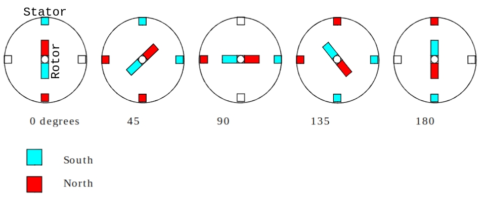
The electromagnets (coils) in the stator can be energized in sequence as shown above. This causes the rotor to rotate. The image above is a simplified electromagnetic view of the machine. The stator coils for a bipolar motor are driven as shown below.

The full bridge connected to motor terminals A,B allow current to be driven through the coil in either direction. A second full bridge drives motor terminals C,D. These electronic bridges could be built using individual transistors but in this case an SN754410NE was used as shown below.
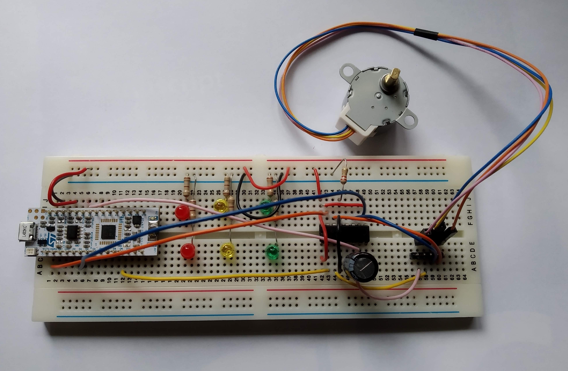
Control pulses for the motor were generated using an STM32L432 Nucleo board which is equipped with a sophisticated motor control timer.
The the motor is driven using a simple sequence of pulses it will indeed rotate however it will exhibit torque pulsations as the motor steps between the stator magnetic poles. These pulsations can be reduced if sinusoidal PWM is used to drive the stator coils. A phase difference of 90 degrees is required between each of the motor coil waveforms.
In order to generate the sinusoidal PWM signal a lookup table was constructed using the following Octave code
clear
scalefactor=1999;
ts=1000;
anglestep=2*pi/ts;
angles=0:anglestep:2*pi-anglestep;
waveform=sin(angles);
lookup=scalefactor+(scalefactor*waveform);
fid=fopen('lookup.h','w');
fprintf(fid,'const uint16_t ScaleFactor=%d;\n',2+2*scalefactor);
fprintf(fid,'const uint16_t SineArray[]={');
for i=1:length(lookup)
  fprintf(fid,'%d',floor(lookup(i)+1));
  fprintf(fid,',\n');
end
fprintf(fid,'};');
fclose(fid);
This code creates a file called lookup.h which is included in a C file that controls the timer. A section of this C file is shown below.
const uint32_t SampleCount = sizeof(SineArray)/sizeof(uint16_t);
volatile uint32_t SampleCounter1 = 0;
volatile uint32_t SampleCounter2 = (SampleCount/4); // start SampleCounter2 a quarter cycle (90) ahead of SampleCounter1
void initTimer()
{
  // see github link for this code
}
void TIM1_UE_Handler(void)
{
/*
 * Warning: it is really important to do something that consumes a few clock cycles in this ISR after the interrupt flags are cleared
 * see : https://developer.arm.com/documentation/ka003795/latest
 */

	TIM1->SR =0; //
	TIM1->CCR1 = SineArray[SampleCounter1];
	SampleCounter1++;
	if (SampleCounter1 >= sizeof(SineArray)/2)
	{
		SampleCounter1 = 0;
	}
	TIM1->CCR2 = SineArray[SampleCounter2];
	SampleCounter2++;
	if (SampleCounter2 >= sizeof(SineArray)/2)
	{
		SampleCounter2 = 0;
	}
	GPIOB->ODR ^= BIT3; // Toggle green LED
}
At the end of each PWM interval, a new value is loaded into the counter compare register for each of the two channels used. Both counter compare channels reference the same sine lookup table using separate indices which are shifted the equivalent of 90 degrees apart.
The current drawn by the SN754410 driver is shown below:

This current waveform is effectively the absolute a value of the current in each stator coil plus quiescent current. Due to the overlap it appears to be 4 times faster than the actual motor coil currents which run at approx 2Hz. The motor runs without any significant torque pulsations. If current control were used these pulsations would probably be reduced further.
Full source code can be found over here on github.
