The (unofficial) Dublin Maker Badge for 2022 will hopefully be based on an NRF52833 module. I got hold of couple and asked a colleague to make a breakout PCB for it to allow me experiment.
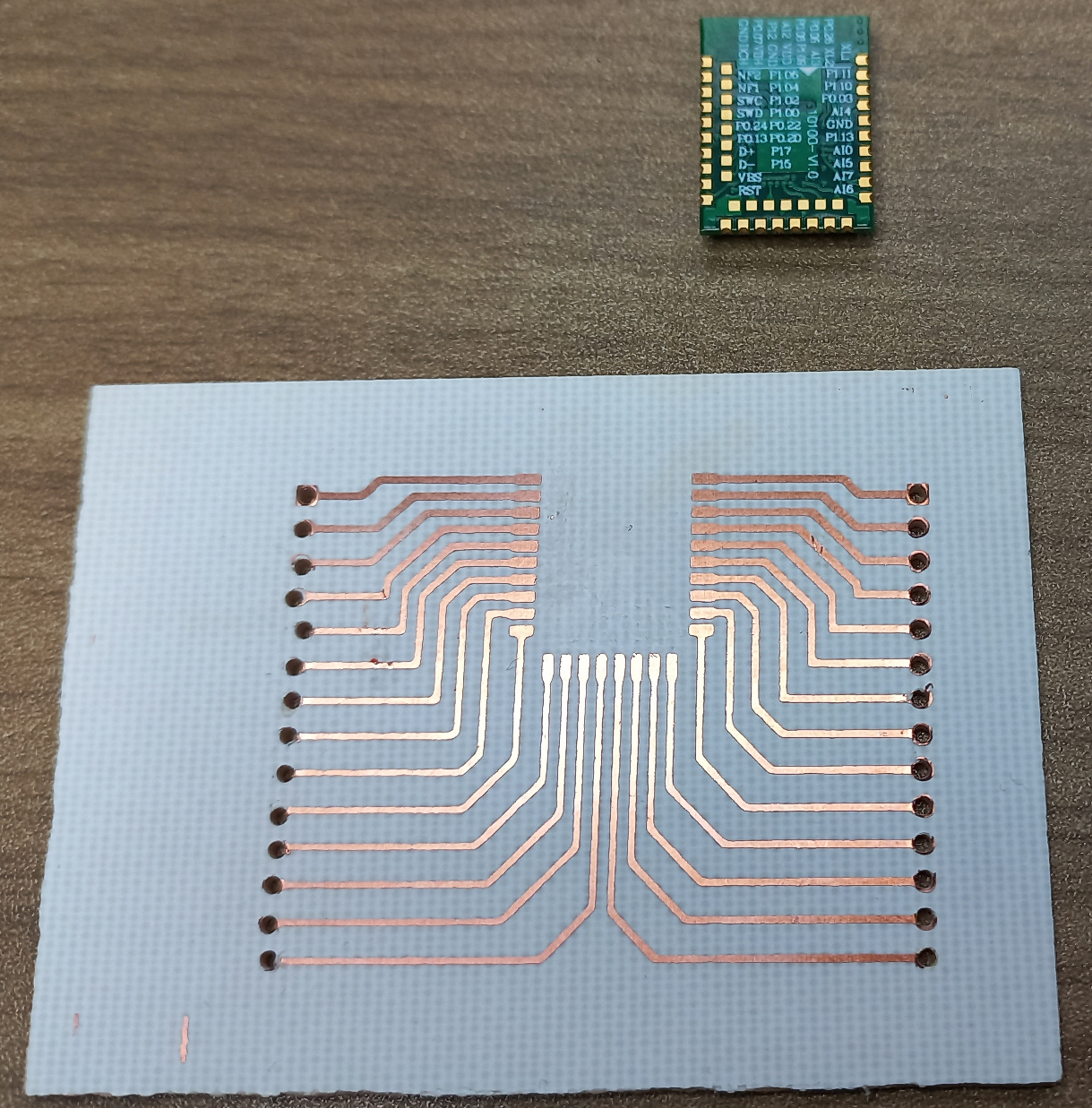
The PCB is a little rough but is OK for evaluation purposes. I won’t be using the inner layer of contacts for the module as I can’t solder on to them manually however I should have enough pins in what remains. Luckily the extremely flexible NRF52833 allows for routing of signals to just about any pin. Next step is to the module to the board.
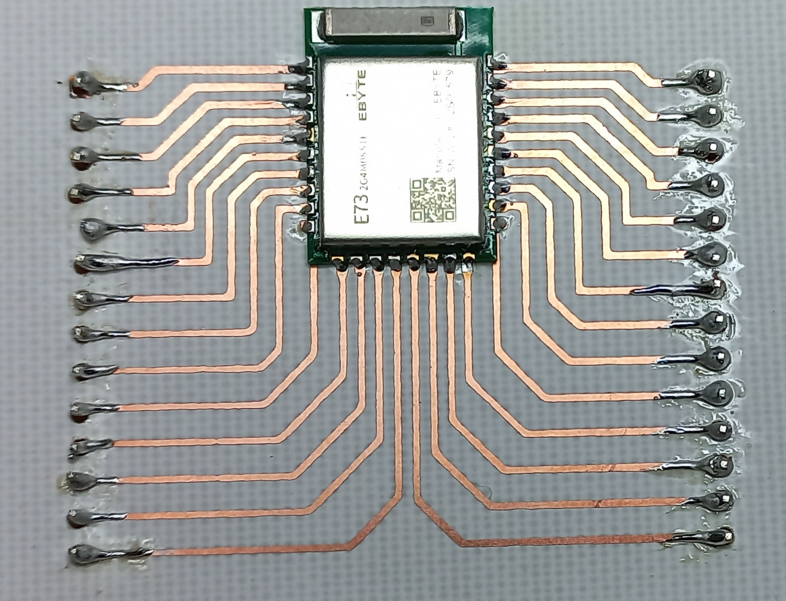
The drill holes for the pin headers have more or less wiped out all of the pads for the pin headers but with some careful soldering I think I got everything wired up. Next step Blinky!

VDD and VDDH are connected to a 3.3V DC supply; the SWD interface is connected to a JLink EDU probe. A simple Zephyr based LED Blinky program was downloaded and tested. The JLink software complained a little about the SWD interface being unstable and it automatically dropped its speed to a lower value. Blinky seemed to work fine; how about a simple BLE example I previously used on the BBC Microbit V2? Well that worked fine too without any changes 🙂
Next step: Interface with a display to see if the SPI interface can be operated at full speed.

