I’ve been struggling with this demonstrator of assembler on the LPC1114 for a while but finally cracked it (on a train ride across the country :). Hope this is instructive to somebody. I think I have stripped the assembler directives down as much as possible, if you find a mistake please comment below.
// Minimal assembler blinky example for LPC1114FN28
// This program flashes an LED on and off. It is used as a
// demonstrator for class work
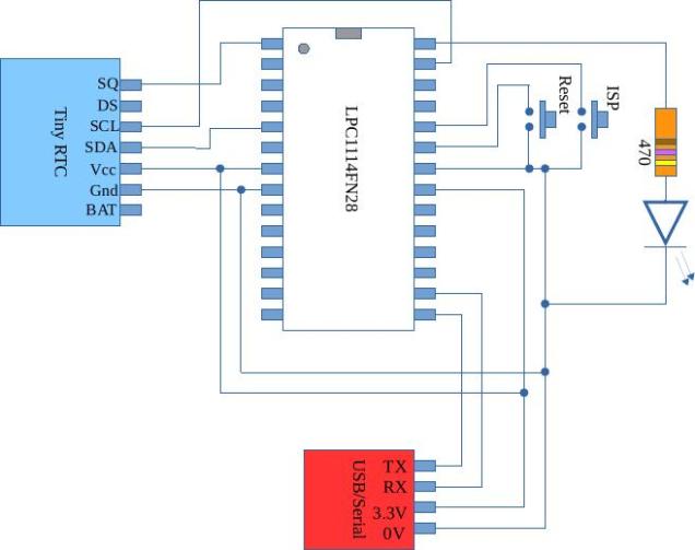
// LED is on GPIO0 bit 2
.syntax unified
.cpu cortex-m0 // Which variant we are using
.thumb /* Cortex micros only understand thumb(2) code */
.global Vector_Table, start
/* Set up interrupt vector table */
.text
/* It would seem that the LPC1114FN28 treats the area of flash used by
the first 16 vectors as special. If you attempt to place code here
it doesn't work so you must either skip past this space or just place
dummy values here */
Vector_Table:
.word 0x10001000 /* Top of Stack */
.word start /* Reset Handler */
.word 0 /* NMI */
.word 0 /* Hard Fault */
.word 0 /* Reserved */
.word 0 /* Reserved */
.word 0 /* Reserved */
.word 0 /* Reserved */
.word 0 /* Reserved */
.word 0 /* Reserved */
.word 0 /* Reserved */
.word 0 /* SVC */
.word 0 /* Reserved */
.word 0 /* Reserved */
.word 0 /* PendSV */
.word 0 /* SysTick */
/* the program starts here */
.thumb_func // The LSB of the address of thumb instructions is
// required to be 1 - the LSB is used as a flag to
// indicate thumb instructions are being used.
// The Cortex M series of processors only understand
// thumb instructions so if PC is loaded with an
// address with LSB = 0 then this is treated as an
// an illegal instruction
// the .thumb_func directive forces the LSB of
// 'start' to be 1
start:
// Do initial IO configuration
// Turn on the clocks for GPIO and IOCON
ldr R1,SYSAHBCLKCTRL // make pointer to register
ldr R0,[R1] // read current value
ldr R2,SYSAHBCLKMASK // read desired bit pattern
orrs R0,R0,R2 // combine with register contents
str R0,[R1] // write back to register
// Make sure pin 25 behaves as a GPIO
ldr R1,IOCON_PIO0_2 // make pointer to register
ldr R0,[R1] // read current value
ldr R2,IOCONMASK // read desired bit pattern
bics R0,R0,R2 // combine with register contents
str R0,[R1] // write back to register
// Make pin 25 behave as an output
ldr R1,GPIO0DIR // make pointer to register
ldr R0,[R1] // read current value
ldr R2,GPIO0MASK // read desired bit pattern
orrs R0,R0,R2 // combine with register contents
str R0,[R1] // write back to register
// Now enter the main loop
main_loop:
// Set bit 2
ldr R1,GPIO0DATA // make pointer to port data register
ldr R0,[R1] // read current value
ldr R2,GPIO0MASK // read bit pattern
orrs R0,R0,R2 // set bits
str R0,[R1] // write new value
bl delay // Leave the LED on for a while
// clear bit 2
ldr R1,GPIO0DATA // make pointer to port data register
ldr R0,[R1] // read current value
ldr R2,GPIO0MASK // read mask
bics R0,R0,R2 // clear bits
str R0,[R1] // write new value
bl delay // Leave the LED on for a while
b main_loop /* branch back to start of loop */
delay: ldr R3,DELAYLENGTH
delay_loop:
subs R3,R3,#1
bne delay_loop
bx LR
// Constants go below here
.align 2 /* Must force realignment again here */
GPIO0DATA: .word 0x50003ffc
GPIO0DIR: .word 0x50008000
SYSAHBCLKCTRL: .word 0x40048080
IOCON_PIO0_2: .word 0x4004401c
SYSAHBCLKMASK: .word 0x10040
IOCONMASK: .word 0x3
GPIO0MASK: .word 0x04
NOTGPIO0MASK: .word 0xfffffffb
DELAYLENGTH: .word 0xfffff
The Linker script file is as follows:
MEMORY
{
    flash : org = 0x00000000, len = 32k
    ram : org = 0x10000000, len = 4k
}

SECTIONS
{

	. = ORIGIN(flash);
        .text : {
		  *(.vectors); /* The interrupt vectors */
		  *(.text);
        } >flash
	. = ORIGIN(ram);
        .data : {
	  INIT_DATA_VALUES = LOADADDR(.data);
	  INIT_DATA_START = .;
	    *(.data);
	  INIT_DATA_END = .;
        } >ram AT>flash
	BSS_START = .;
	.bss : {

	    *(.bss);

	} > ram
	BSS_END = .;
}
And finally the makefile is
# Specify the compiler to use
CC=arm-none-eabi-gcc
# Specify the assembler to use
AS=arm-none-eabi-as
# Specity the linker to use
LD=arm-none-eabi-ld

CCFLAGS=-mcpu=cortex-m0 -mthumb -g
ASFLAGS=-mcpu=cortex-m0 -mthumb -g --warn
# List the object files involved in this project
OBJS=	blinky.o
blinky.elf : $(OBJS)
	$(LD) $(OBJS) -T linker_script.ld --cref -Map blinky.map -nostartfiles -o main.elf
	 objcopy -O ihex main.elf main.hex
blinky.o: blinky.s
	$(AS) $(ASFLAGS) blinky.s -asghl=blinky.lst -o blinky.o
# if someone types in 'make clean' then remove all object files and executables
# associated wit this project
clean:
	rm $(OBJS)
	rm blinky.elf