An 8 digit VFD for the ESP32

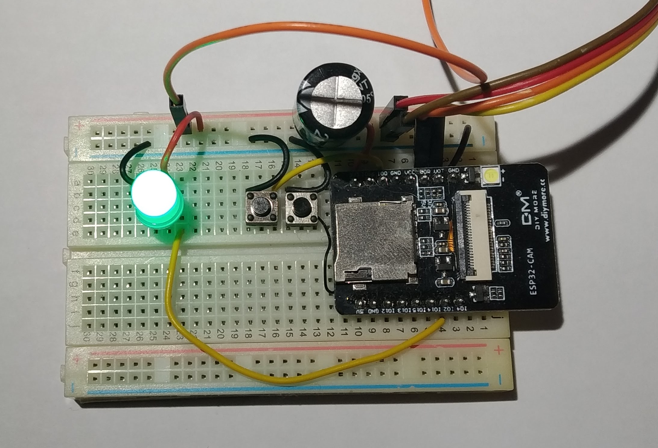
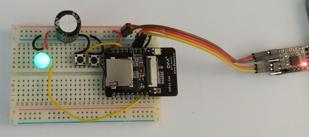
I got hold of a Vacuum Fluorescent Display module from Aliexpress. It comes in two versions : one with an SPI interface, one without. I went with the SPI interface version. The display reminded me of a clock radio I had growing up so it was natural to put it to work as a clock. I wired it to an ESP32-CAM module as shown below:

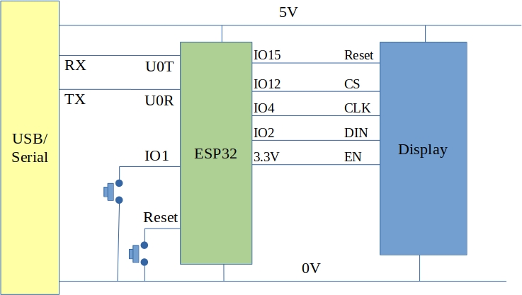
Details about how the display is programmed were found over here. I wanted to use the SPI hardware interface instead of bit-banging the data and so developed the following program using Arduino for ESP32:

#include <SPI.h>
#include <WiFi.h>
#include <NTPClient.h>
#include <HTTPClient.h>

/*
  ESP32 based clock.
  Uses Vacuum Fluourescent Display (VFD)
  Gets time from an NTP server
*/

WiFiUDP ntpUDP;
NTPClient timeClient(ntpUDP);

const char* ssid = "***********";
const char* password =  "****************";

class VFDisplay
{
  public:
    VFDisplay() {};
  void begin()
  {     
    SPI.begin(SCK,MISO,MOSI,SS);
    pinMode(Reset,OUTPUT);
    pinMode(CS,OUTPUT);
    digitalWrite(Reset, LOW);
    delayMicroseconds(5);
    digitalWrite(Reset, HIGH);
    
    setDigitCount(8);
    setBrightness(127);    
    Serial.printf("VFD_init\n");
  }  
  void putChar(unsigned char x, char chr)
  {
    digitalWrite(CS, LOW); 
    writeDisplay(0x20 + x); 
    writeDisplay(chr);
    digitalWrite(CS, HIGH); 
    show();    
  }
  void printString(char *str)
  {
    int x = 0;
    while(*str)
    {
      putChar(x++,*str++);
    }
  }      
  private:
  void setDigitCount(uint8_t count)
  {
      digitalWrite(CS, LOW);
      writeDisplay(0xe0);
      delayMicroseconds(5);
      writeDisplay(count-1);
      digitalWrite(CS, HIGH);
      delayMicroseconds(5);  
  }
  void setBrightness(uint8_t brightness)
  {
    digitalWrite(CS, LOW);
    writeDisplay(0xe4);
    delayMicroseconds(5);
    writeDisplay(brightness);
    digitalWrite(CS, HIGH);
    delayMicroseconds(5);
  }
  void show()
  {    
    digitalWrite(CS, LOW);
    writeDisplay(0xe8);     
    digitalWrite(CS, HIGH); 
  }
  void writeDisplay(uint8_t b)
  {
    SPI.beginTransaction(SPISettings(1000000, LSBFIRST, SPI_MODE0));
    SPI.write(b);
    SPI.endTransaction();
  }

  uint8_t Reset=15;
  uint8_t CS = 12;
  uint8_t SCK = 4;
  uint8_t MOSI = 2;
  uint8_t MISO = 1;
  uint8_t SS = 12; // not actually used - see CS above

};

VFDisplay vfdisplay;
void setup() {
    
  Serial.begin(115200);  
  vfdisplay.begin();
  WiFi.begin(ssid, password);
  while (WiFi.status() != WL_CONNECTED) {
    vfdisplay.printString("WifiWait");    
    delay(1000);    
  }
  vfdisplay.printString("WifiDone");
  timeClient.begin();
  timeClient.setTimeOffset(3600);
  timeClient.update();
  timeClient.setUpdateInterval(5*60*1000); // update from NTP only every 5 minutes  
}

void loop() {
  timeClient.update();     // This will only go to the Internat if the update interval has passed (set to 5 minutes above)
  String timeString = timeClient.getFormattedTime();
  char TimeCharArray[20];
  timeString.toCharArray(TimeCharArray,19);
  vfdisplay.printString(TimeCharArray);
  delay(100);
}

The system appears to work well and could be extended to include a Bluetooth interface to set an alarm time or time zone etc.

Green power

The operators of the national grid in Ireland provide information about the fuel mix used for electrical power generation. This is updated every 15 minutes and can be seen here http://www.eirgridgroup.com/how-the-grid-works/system-information/

Delving into the source for this page a little it is possible to locate the web resource for the fuel mix which, it turns out, returns data in JSON.

So, a little bit of building later….

ESP32 with a PL9823 LED

Followed by a little bit of coding:

#include <ArduinoJson.h>
#include <WiFi.h>
#include <HTTPClient.h>
#include <SPI.h>
const char* ssid = "XXXXXXXXX";
const char* password =  "XXXXXXXXXX";
StaticJsonDocument<1024> doc; 
#define COAL 0
#define GAS 1
#define IMPORT 2
#define OTHER 3
#define RENEW 4
float coal, gas, import, other, renew;
float domestic;

void setup() {
  SPI.begin(1, 4, 2, 3); // (int8_t sck, int8_t miso, int8_t mosi, int8_t ss)
  Serial.begin(115200);
  
  delay(1000);
  WiFi.begin(ssid, password);

  while (WiFi.status() != WL_CONNECTED) {
    Serial.println("Connecting to Wifi");
    writePL9823(0x00);
    delay(1000);
    writePL9823(0xffff00);
    delay(1000);    
  }
  Serial.println("Wifi ready");
  
}

void loop() {
  // put your main code here, to run repeatedly:
  if ((WiFi.status() == WL_CONNECTED)) { //Check the current connection status

    HTTPClient http;

    // Interesting discovery : setting the date/time to a future data returns the latest value
    http.begin("http://smartgriddashboard.eirgrid.com/DashboardService.svc/data?area=fuelmix&region=ALL&datefrom=17-Dec-2050+23:59&dateto=17-Dec-2050+23:59"); //Specify the URL
    int httpCode = http.GET();                                        //Make the request

    if (httpCode > 0) { // Http error?

      String payload = http.getString();
      Serial.println(httpCode);
      Serial.println(payload);
      deserializeJson(doc, payload);
      coal = doc["Rows"][COAL]["Value"];
      gas = doc["Rows"][GAS]["Value"];
      import = doc["Rows"][IMPORT]["Value"];
      other = doc["Rows"][OTHER]["Value"];
      renew = doc["Rows"][RENEW]["Value"];
      domestic = coal + gas + other + renew;
      Serial.print("Total (without export)= ");
      Serial.println(domestic);
      Serial.print("Renew = ");
      Serial.println(renew);
      Serial.print("% = ");
      Serial.println(renew / domestic);
      if ( (renew / domestic) > 0.5)
      {
        writePL9823(0x00ff00);
      }
      else
      {
        writePL9823(0xff0000);
      }
      delay(15 * 60 * 1000); // wait 15 minutes as that is the update interval
    }
    else {
      Serial.print("HTTP Error ");
      Serial.println(httpCode);
      writePL9823(0xff);
      delay(10000);
    }
    http.end(); //Free the resources
  }
}

void writePL9823(uint32_t Colour)
{
  // each colour bit should map to 4 SPI bits.
  // Format of Colour (bytes) 00RRGGBB
  uint8_t SPI_Output[12];
  int SrcIndex = 0;
  int DestIndex = 0;
  for (DestIndex = 0; DestIndex < 12; DestIndex++)
  {
    if (Colour & (1 << 23))
    {
      SPI_Output[DestIndex] = 0xe0;
    }
    else
    {
      SPI_Output[DestIndex] = 0x80;
    }
    Colour = Colour << 1;
    if (Colour & (1 << 23))
    {
      SPI_Output[DestIndex] |= 0xe;
    }
    else
    {
      SPI_Output[DestIndex] |= 0x8;
    }
    Colour = Colour << 1;
  }
  SPI.beginTransaction(SPISettings(2000000, MSBFIRST, SPI_MODE0));
  SPI.transfer(SPI_Output, 12);
  delay(10);
  SPI.endTransaction();
}

And hey presto!

A traffic light which is green when renewable power on the grid is greater than 50%, red otherwise. This could inform you when is a good time to turn on the clothes dryer for example.

I wouldn’t recommend that this be used to control devices directly as there are many ways it could be hacked.

Controlling a PL9823 LED over Bluetooth LE

I received an ESP32-Camera board from Aliexpress recently but unfortunately it’s camera was broken (the supplier is sending a free replacement). Not wanting to waste the otherwise good ESP32 I decided to see if it could be used to control the brightness and colour of an LED such as the PL9823. These LED’s are controlled using a serial data string which is documented elsewhere in this blog (https://ioprog.com/2016/04/09/stm32f042-driving-a-ws2812b-using-spi/ and https://ioprog.com/2018/11/08/stm32l031-controlling-a-pl9823-led-using-spi/)

It turned out to be pretty straightforward.

The ESP32 board was connected to the PC over a USB-Serial converter. Two buttons were added to control boot mode and the PL9823’s Data In pin was connected to IO2. The code to control all of this was developed in the Arduino environment (based off an example) and is as follows:

#include <SPI.h>

/*
 *  Controlling a PL9823 LED over bluetooth on an ESP32
    Based on Neil Kolban example for IDF: https://github.com/nkolban/esp32-snippets/blob/master/cpp_utils/tests/BLE%20Tests/SampleWrite.cpp
    Ported to Arduino ESP32 by Evandro Copercini
*/

#include <BLEDevice.h>
#include <BLEUtils.h>
#include <BLEServer.h>

#define SERVICE_UUID        "22389e17-7cee-41ce-8aa0-28a4482f7020"
#define CHARACTERISTIC_UUID "a575e1bf-e15f-4534-a80c-1837348360ad"

void writePL9823(uint32_t Colour)
{
    // each colour bit should map to 4 SPI bits.
    // Format of Colour (bytes) 00RRGGBB
    uint8_t SPI_Output[12];
    int SrcIndex = 0;
    int DestIndex = 0;
    for (DestIndex = 0; DestIndex < 12; DestIndex++)
    {
        if (Colour & (1 << 23))
        {
            SPI_Output[DestIndex] = 0xe0;
        }
        else
        {
            SPI_Output[DestIndex] = 0x80;
        }
        Colour = Colour << 1;
        if (Colour & (1 << 23))
        {
            SPI_Output[DestIndex] |= 0xe;
        }
        else
        {
            SPI_Output[DestIndex] |= 0x8;
        }
        Colour = Colour << 1;
    }    
    SPI.beginTransaction(SPISettings(2000000, MSBFIRST, SPI_MODE0)); 
    SPI.transfer(SPI_Output, 12);
    delay(10);
    SPI.endTransaction();
}

class MyCallbacks: public BLECharacteristicCallbacks {
    void onWrite(BLECharacteristic *pCharacteristic) {
      std::string value = pCharacteristic->getValue();
    
      if (value.length() > 0) {
        // Write debug messages out to serial port
        Serial.println("*********");
        Serial.print("New value: ");
        for (int i = 0; i < value.length(); i++)
          Serial.print(value[i]);

        Serial.println();
        Serial.println("*********");
        // update the PL9823 LED
        uint32_t intvalue;
        intvalue = strtoul(pCharacteristic->getValue().c_str(),NULL,16);
        writePL9823(intvalue);
      }
    }
};

void setup() {
  
  SPI.begin(1,4,2,3); // (int8_t sck, int8_t miso, int8_t mosi, int8_t ss)
  Serial.begin(115200);  
  Serial.println("Connect to the device over BLE and change the colour of the LED");

  BLEDevice::init("BLE_PL9823");
  BLEServer *pServer = BLEDevice::createServer();

  BLEService *pService = pServer->createService(SERVICE_UUID);

  BLECharacteristic *pCharacteristic = pService->createCharacteristic(
                                         CHARACTERISTIC_UUID,
                                         BLECharacteristic::PROPERTY_READ |
                                         BLECharacteristic::PROPERTY_WRITE
                                       );

  pCharacteristic->setCallbacks(new MyCallbacks());

  pCharacteristic->setValue("ffffff");
  
  pService->start();

  BLEAdvertising *pAdvertising = pServer->getAdvertising();
  pAdvertising->start();

  // Write the initial value out to the PL9823
  uint32_t intvalue;
  intvalue = strtoul(pCharacteristic->getValue().c_str(),NULL,16); 
  writePL9823(intvalue);
}
void loop() {
  // put your main code here, to run repeatedly:
  
  delay(1000);
}

Using an Andoid app like BLE Scanner, it is possible to control the the LED by sending a hex string such as ff0000 for maximum red; 00ff00 for max green and 0000ff for max blue. These colours can be mixed to form arbitrary colours and brightness.

ESP32 and LoRa

ESP32_SX1278Module

Hardware

The ultimate intention of this project is to set up a LoRa to TCP/IP gateway. I decided that the ESP32 would make a good bridging device and found one here for about €6. The LoRa transceivers were obtained from Aliexpress also and are available here. Interfacing with the ESP32 was pretty straightforward as the LoRa module simply connects to its SPI interface. The really tricky part was connecting up to the 1/20 inch pitch connector on the LoRa module.

Software

I decided to develop my own LoRa driver module for the ESP32. Its API is based on the equivalent library for Arduino (I felt it would be easier to deal with just one API). Code was developed using the ESP development environment and is available here

Sender

Every conversation needs at least two parties so a device was needed to send some test data to the ESP32 board. A Seeduino was connected to an SX1278 LoRa module as shown here:
seeduino_lora
The great thing about the Seeduino is that you can switch its I/O to 3.3V which allows you directly connect it to the SX1278 module. The code (which makes use of the Arduino SX1278 library) is as follows:

#include <SPI.h>
#include <LoRa.h>

int counter = 0;

void setup() {
  Serial.begin(9600);
  delay(1000);
  //while (!Serial);

  Serial.println("LoRa Sender");
  // override the default CS, reset, and IRQ pins (optional)
  LoRa.setPins(7, 5, 6); // set CS, reset, IRQ pin


  if (!LoRa.begin(433123000)) {
    Serial.println("Starting LoRa failed!");
    while (1);
  }
  // The following settings should maximize reliability
  LoRa.setTxPower(20); // going beyond 10 is illegal
  LoRa.setSpreadingFactor(12);
  LoRa.setSignalBandwidth(125000);
  LoRa.setCodingRate4(5);
  pinMode(2,OUTPUT);
  Serial.println("Setup done");

}

void loop() {
  Serial.print("Sending packet: ");
  Serial.println(counter);
  digitalWrite(2,HIGH);
  // send packet
  LoRa.beginPacket();
  LoRa.print("hello ");
  LoRa.print(counter);
  LoRa.endPacket();
  digitalWrite(2,LOW);
  counter++;

  delay(4000);
}

Testing

The main performance measure I was concerned with was range as the data sizes were very small. The Arduino end of the radio link used the coiled quarter wavelength antenna supplied with the module. The ESP32 end used a straight quarter wavelength monopole. Range testing consisted of me walking around the neighborhood with the Arduino end in a bag while talking with my sons over the phone while they watched the ESP32 end. The ESP32 “base station” was located inside a house with foil backed insulation (which didn’t help). The testing was carried out in a suburban area with lots of houses, trees, cars and so on.

Results and discussion

The best range I managed to get was 770m (measured on Google maps). I suspect that this can be improved if I switch to dipole antennas and if I locate outside the foil envelope of the house. Watch this space 🙂