Disco Fever!

I have been working on a spectrum analyzer based on the STM32F303 Nucleo.  The analyzer uses a 16 LED WS2812B led ring to output spectrum data.  There were lots of interesting things on the way.

First of all, it seems that there are times when you should use gcc as your linker rather than ld.  It would appear that there are lots of options and switches built into gcc which it quietly passes on to the linker.  This tripped me up when specifying floating point options and specifying the FPU type.  After LOTS of fiddling and searching of mailing lists the problem was solved and the Makefile contains the necessary switches for the FPU and floating point libraries to all work together.

During the course of this project I tried to use the CMSIS fft functions – after all, they are optimized for ARM by ARM.  Sadly this didn’t work out because the 64k for flash memory in the STM32F303 isn’t big enough apparently.  I reverted to an fft function I’ve been using for years now on other MCU’s.  Its a lot smaller and executes quickly enough : the signal processing time for 512 samples is about 8.5ms.

Finally, the last hurdle to be overcome involved the WS2812B’s.  In a previous post I described the use of the STM32F042 with the WS2812 ring.  This MCU runs at 48MHz making it easy to generate a 3MHz SPI bus frequency : just divide by 16.  The STM32F303 however runs at 64MHz and only certain divisors are available (8/16/32 etc).  Initially I tried running the SPI at 2MHz and this worked for one or two LED’s however it did not work well for 16.  4MHz was then tried and its seems its ok although there is some flicker with certain combinations of LED colours.

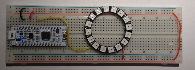
The circuit.

Wiring


The video

The video below shows the STM32F303 performing a live FFT and controlling a WS2812 LED ring. The LED ring is driven as follows:
At the 6 o’clock position is low frequency. As you move anti-clockwise around the ring, each LED represents a higher frequency component.  Each LED represents a step of 128Hz so 2048Hz is the maximum frequency shown.  The system samples at 32768Hz however most of the music energy is at the lower end of the spectrum.  The LED ring is showing a “zoomed in” version of the spectrum

The LED colours change as follows (16 steps):
Blue : low magnitude
Yellow-Green : medium magnitude
Red : large magnitude


The music is from the Free Music Archive.  The track is Pianoman Sofa by Lobo Loco.


The code

The code is available on github at the link below.

https://github.com/fduignan/DiscoFever.git


Using SPI and DMA to drive 3 WS2812Bs with an STM32F042 Nucleo

As promised in a previous post, this example drives 3 WS2812B’s using DMA to SPI.  It also shows that interrupts can happen at the same time without affecting the performance of the LED’s.

IMG_20160409_213853729

Three LED’s are controlled and, as expected, the burst of SPI data lasts 72 microseconds.

SPIDMAWaveform

The program outputs a simple RGB pattern that moves across the LED’s.  The program is deliberately slowed down to allow us see the changing colours.  The program also outputs a message over the UART to the host PC using an interrupt driven serial transmit routine which demonstrates that the solution is tolerant of interrupts.

A video of the program in action is over on YouTube.

Code may be downloaded over here on Github

STM32F042 driving a WS2812B using SPI

IMG_20160408_173534855

The WS2812B is an RGB LED with a built in serial interface.  They are available from a number of sources.  The ones used in this project were obtained from dx.com and cost about 6 Euro for a pack of 5.  These are mounted on a nice little breakout board.  Pins can be soldered on allowing them to be plugged into a breadboard as shown above.

Driving a WS2812B requires some delicate timing.  It has a serial interface that represents 1’s and 0’s using a particular waveform rather than a simple high or low.  A ‘1’ is represented by a high-low pulse with the high pulse lasting about twice as long as the low pulse.  A ‘0’ is represented with a high-low pulse also though in this case, the low pulse is twice the width of the high pulse. The datasheet also specifies maximum and minimum widths for pulses.  Roughly speaking, the high-low waveform must be completed in about a microsecond.  I noticed that there were some solutions online that used SPI to generate the serial waveforms and decided to try it out on the STM32F042 Nucleo.

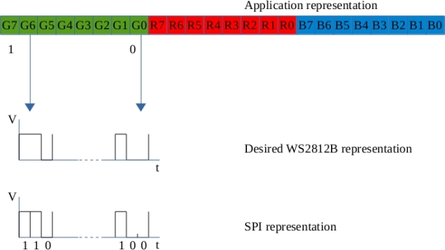
The first step was to figure out the mapping of RGB colour values to SPI bytes.  Note: The WS2812B orders the colours as Green Red Blue so I will be using the term “GRB colour value” below.  The WS2812B must be sent a 24bit colour value followed by a low signal of a least 50 microseconds.  Conceptually I think of this as filling a 24 bit shift register and then latching the contents through to the LED’s.  The data is translated to SPI bytes as shown below:

bit_conversion

The WS2812B datasheet contains the following specifications for the waveforms.

WS2812B Logic 1:

A high pulse of 0.8us +/-150ns followed by a low pulse of 0.4us +/-150ns

Total width : 1.25us +/-600ns

WS2812B Logic 0:

A high pulse of 0.4us +/-150ns followed by a low pulse of 0.8us +/-150ns

Total width : 1.25us +/-600ns

If the SPI bus is run at 3MHz, one SPI bit lasts 0.333us, two SPI bits take 0.667us. These times are within the WS2812B specification for narrow and wide pulse widths. A colour bit value of ‘1’ in the application layer is mapped to an SPI bit pattern of ‘110’; while a colour bit value of ‘0’ in the application layer is mapped to an SPI bit pattern of ‘100’. Each application colour byte therefore maps to 3 SPI bytes. A 3 byte Green-Red-Blue colour value in the application layer is converted to a 9 byte SPI sequence and output to the WS2812B.

The SPI output (MOSI) is taken from the pin labelled “A6” on the Nucleo board and connected to Din (Data In) on the WS2812B breakout board.

A demonstrator application generates a Green/Red/Blue colour value that changes over time. This value is converted to a 9 byte SPI array and output to the WS2812B. A video showing the colour progression is available on YouTube . Note. The LED is covered with a piece of quartz to dim it a little (the camera didn’t like it being so bright).

Code is available on GitHub and was compiled using arm-gcc 4.9.3.  OpenOCD was used to download and debug.  Next step is to drive a string of these using DMA and SPI 🙂