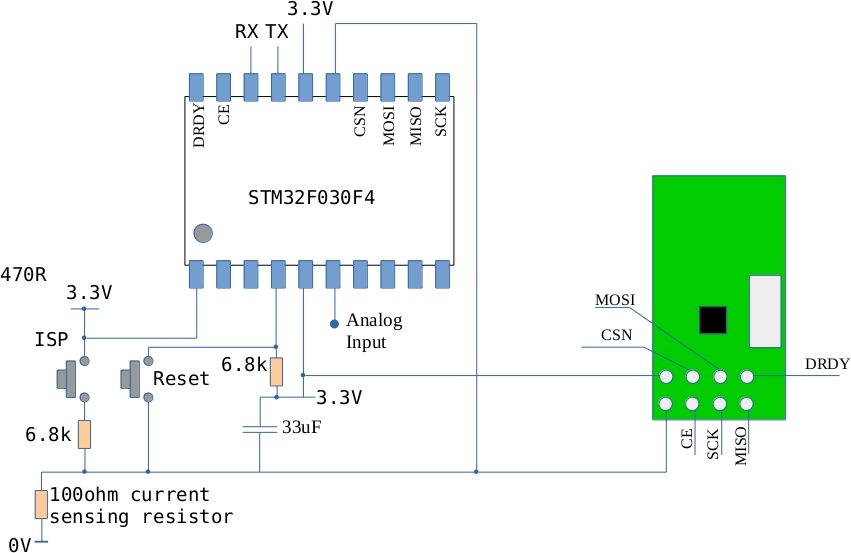
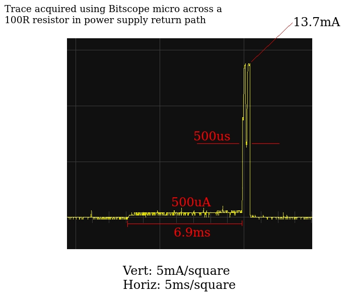
I finally achieved a target run time (estimated) of a year on a couple of AAA batteries for the NRF24L01 and the STM32F030. The current flow is mostly zero but once a second the MCU wakes up and transmits a message leading to a current waveform like this:
The best estimate I can come up with for the average current flow puts it below 100uA which should allow very long run times off a pair of AAA batteries.
Code, circuits, results and further discussion is here
Month: August 2015
Using the RTC on the STM32F0 (STM32F030) value line discovery board
I’ve been trying to get the RTC going on the STM32F030Discovery board (The STM32 F0 Value Line Discovery board) with the aim of reducing average current consumption. After quite a struggle I finally figured it out. Demo code can be downloaded here. Next step: apply this a the STMF030/NRF24L01 node
Reducing power consumption on the STM32F030 and the NRF24L01
The original code I used for this circuits consumed as much as 20mA when running. This is way too much for a battery powered application. The main power consumers are of course the NRF24L01 radio and the MCU. The radio current can be reduced significantly if its RF section is turned off when not in use. The scenario I have in mind for this device is that it would periodically measure an analogue signal and transmit the result to a base station. This requires the radio to be on for a very short time (the length of time it takes to send a packet). The remainder of the time, the radio can be in low power standby mode.
The MCU power consumption can be reduced by entering sleep mode and waking up periodically to measure and transmit data. Originally I tried to use the ARM Cortex SysTick interrupt however its power consumption was still too high. In an attempt to reduce power consumption, the AHB Bus clock was reduced (using the prescaler) but it seems that the SysTick timer stops running when you do this. This approach was abandoned and one of the other timers was used to periodically wake the MCU up. The ARM Cortex M0 can enter into two different types of deep sleep mode: regular and deep. In regular sleep mode, the CPU core is stopped but the peripherals continue to receive a clock signal. In deep sleep mode all clocks stop (except the RTC clock – more on this in a later post). If no clocks are running then the periodic wake-up timer will not run either so deep sleep is out for now. This is not too bad a situation however as the regular timers will run quite happily if the AHB bus clock speed is reduced.
The solution
The MCU starts up and, configures ports, ADC and a timer. It also initializes the radio. A measurement is taken and the MCU is put into low power mode. In this mode the MCU core is stopped and the AHB bus clock is reduced to 8MHz/512 ( 15625Hz) and most peripherals are disabled. This greatly reduces power consumption. The timer is configured to generate an interrupt every 5 seconds. The interrupt wakes the MCU core up which accelerates back up to 8MHz, re-enables the various peripherals, takes a measurement, sends data and then goes back to sleep.
Current consumption
The current consumption during sleep drops to 0.57mA (lets call this the quiescent current). The current while awake is difficult to measure using a multimeter however its duty cycle is very low so over time its affect on battery life is probably a lot less than the quiescent current.
Battery life
If the circuit is powered off two AAA batteries in series (3V in total) each with a capacity of 750mAh (typical) then I would expect this circuit to run for about 2 months (it is currently running at 3.3V so the drop to 3V should reduce current a little).
Possible improvements
The radio module is powered down to its lowest level when not in use so without tinkering with the surface mount resistors I can’t see this current decreasing much. It may be possible to reduce the MCU current using the build-in RTC circuit. This has an independent low speed clock that continues to run while the MCU is in a deep sleep mode. There are potentially big savings here!
Code
The current state of the code can be downloaded here – it includes the Intel Galileo node.js code that receives data from the circuit.
