With the Covid-19 pandemic ongoing it is not likely there will be any further Breadboard Games events this year. There was a small event in early March in Kevin St. public library with children from Singe Street primary school. On that day the attendees built a board very similar to the one we used in
St. Audoen’s school in 2017.
So what about the rest of the year? Well, a couple of events happened this year that made me think of a particular game: the passing of John Horton Conway and the pandemic so the game is of course “The game of life”. Lots has been written about this game and I will not repeat that here, instead I will focus on how this can be implemented using a low cost microcontroller (MCU), screen and breadboard. There will likely not be “event” based on this game but maybe a reader will be inspired to try it out for themselves.
The schematic
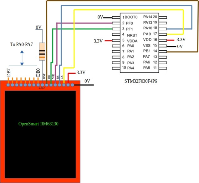
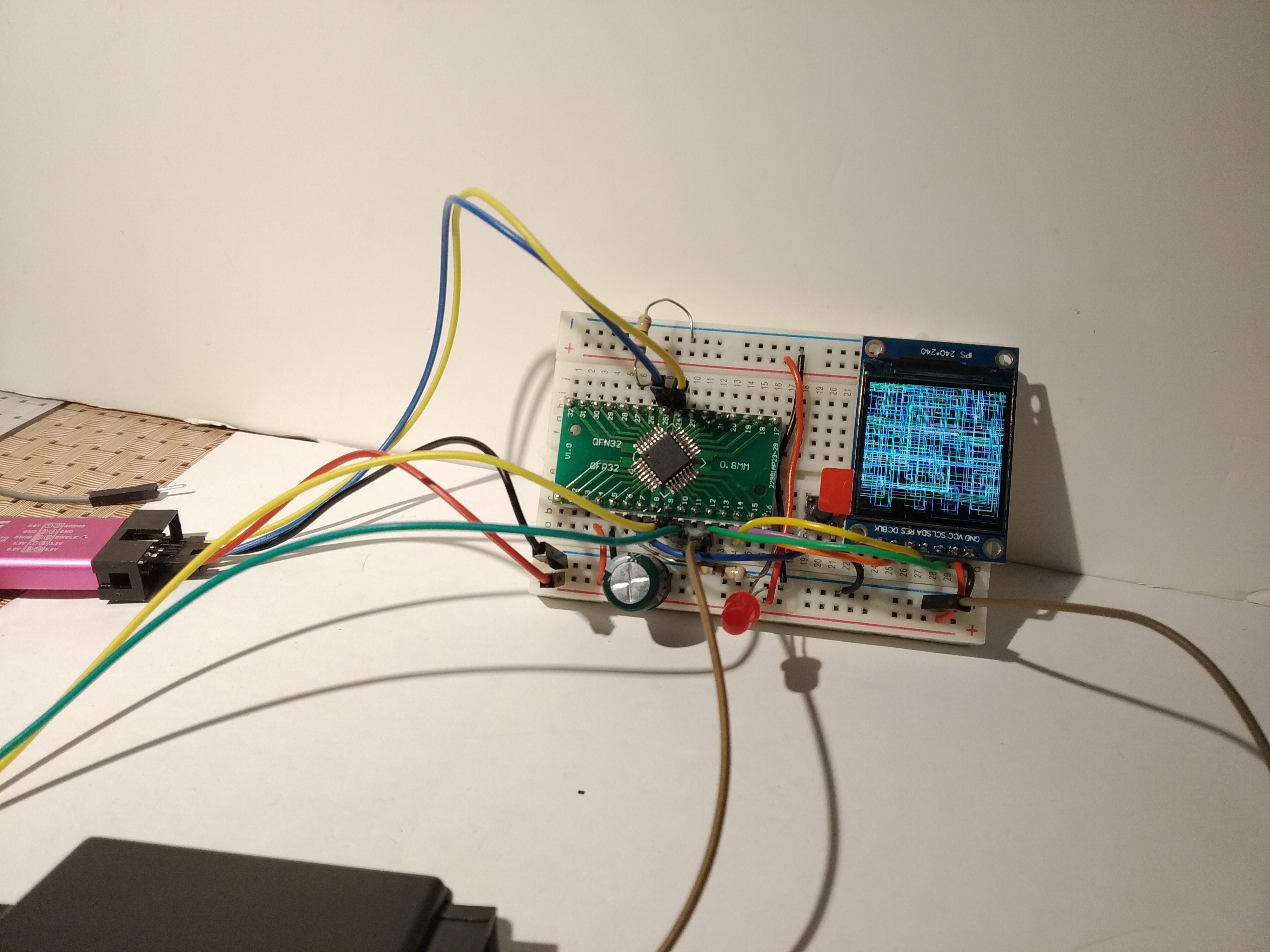
This circuits makes use of components I had lying left over from other breadboard games projects. The MCU is the 30 cent (approx) STM32F030F4P6. This display is a 176×220 TFT board with a parallel interface. The databus runs between PA0-PA7 on the STM32 and DB0-DB7 on the display (it is not shown completely as it would have cluttered the schematic).
The specifications of the MCU are pretty meagre: 16kB of Flash, 4kB of RAM, 48MHz clock speed. All pins have been used to control the display.
The game
Conway’s game of life is all about automata (cells) that live or die depending upon what surrounds them. Cells can die of loneliness (less that 2 neighbours), starvation (more than 3 neighbours) and they can come to life if they are bordered by exactly 3 neighbours. These rules are applied repeatedly to the cells in the landscape. I’ve chosen to do this in two passes. The first pass decides what the state of each cell will be during the next time around based on current state. The second pass switches from the old state to the new state. This of course requires memory (RAM) and this MCU only has 4kB. The display has 176×220 = 38720 pixels. The game allocates one pixel per cell so without some sort of compression there is no way this MCU can store this amount of data. To further add to the storage burden I’ve decided to go with a coloured version of GoL called Quad-Life. Each pixel can be one of 4 colours or black. Where can this be stored?
Stealing memory from the Display
The RM68130 display has enough on-board RAM to store 18bits for each of the 176×220 pixels. All of this does not have to be used for controlling the display however. If the display is switched to 8 colour mode then only 3 of those 18 bits is required per pixel (1 for red, 1 for blue and 1 for green). The remaining 15 bits can be used to hold whatever you like without impacting on what you see on screen. At least that was the theory…. I’ve been using various small displays like this for a while and up until now have had little success reading data back from them. The SPI versions are particularly tricky; some don’t even have read-back functionality. Happily the RM68130 does allow you read back from it’s graphics memory but there’s a catch: the bits you write do not come back to you in the same order. Now I’m willing to accept I may have made a mistake here but I found it VERY confusing reading data back from the display. After many hours I figured out enough to store 1 byte of my choosing alongside each pixel. This means the MCU just got an additional 38720 bytes of RAM – plenty for storing the future states of each cell. By the way there are other displays that should work like this. I’ve tried the ST7775 and the ILI9225 (both parallel interfaces) and they both worked fine
Additional game details
GoL has to start somewhere. You need some way of supplying initial states for the cells (pixels). As you can see above there are no more pins available for user input (PA13 and PA14 are used for debugging). One further feature of the display is that also functions as a resistive touch screen. The user now simply draws the initial state using a stylus (or finger).
The GoL landscape is not meant to run in to a hard border so when a cell goes beyond an edge it “wraps” around to the other side.
Gameplay
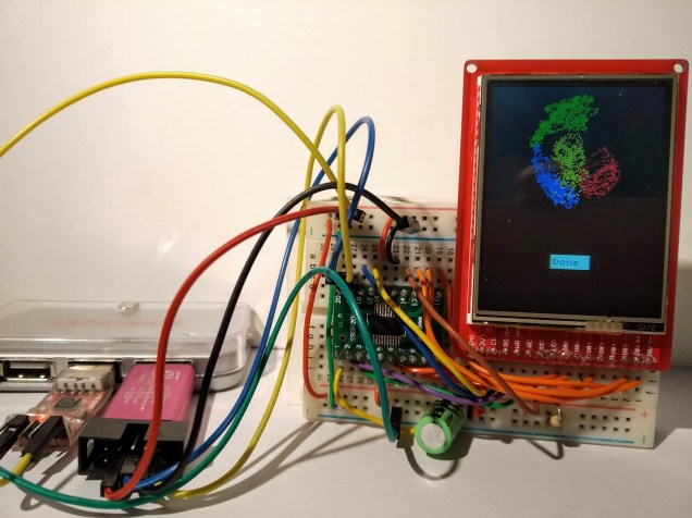
The video below shows the game “in action”. It is not particularly fast and manages about 1 update per second. Consider it a slightly interactive desk ornament 🙂
The code
Code is as usual available over here on Github. There has be no attempt to optimize the performance of this code in any way. It is shown in what is hopefully the easiest to understand mode.

