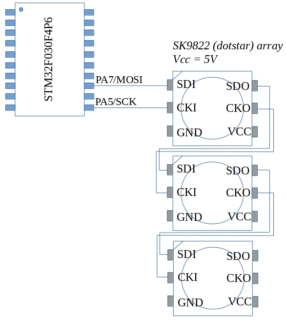
The SK9822 LED (also known as the “dotstar” LED) is a smart RGB LED similar to the WS2812B. It has some advantages however: It is controlled using a standard SPI interface which means it does not rely on the sort of critical timing the WS2812 needed. It also allows you separately control the brightness and the colour mix of the internal LED’s. The LED’s can be strung together; the data and clock output from one feeding the next. The LED’s require use two pins of the host microcontroller: MOSI and SCK as shown in the figure above. Power should be supplied from a separate source to the microcontroller. The SK9822’s are 5V devices but seem to accept 3V logic signals on their control inputs.
The LED’s I got came in the 50/50 surface mount format which makes them a little difficult to use with a breadboard. A TSSOP-20 adapter came in very handy however and I was able to mount 3 on the same board as shown below.
The LED’s are controlled using a data frame that begins with a sequence of the following form
0x00 0x00 0x00 0x00 ii bb gg rr 0xff 0xff 0xff 0xff
The leading 4 zeros are a start of data frame delimiter.
These are followed by a 1 byte intensity or brightness value which ranges from
0 to 31. The most significant 3 bits of the brightness field must be 1
Values in the range 0 to 255 follow for blue green and red
Finally an end of frame consisting of 4 bytes of 0xff is sent.
The test program below outputs signals that cycle 3 LED’s through a range of colours
The program was developed using an STM32F030F4P6 breakout board and ST-Link V2
SWD interface.
Code is available for download from here on github
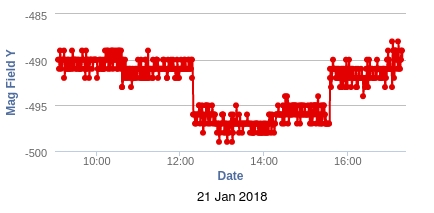
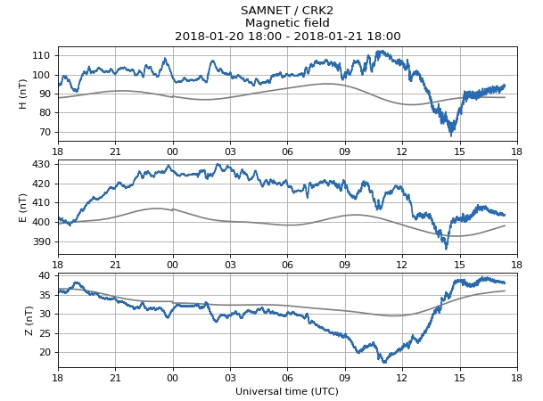
There is a moderate solar storm going on today and I noticed that there was a deflection of the electronic compass output around the same time. This is about the third time I’ve noticed something like this. Aurorawatch UK (https://aurorawatch.lancs.ac.uk/) showed this deflection around the same time:
Now, I know, the units are wrong and the signs are opposite but it is nevertheless a change at around the same time. Furthermore, the temperature of the sensor was stable at 16.7 degrees throughout the whole event so I think I can rule out a temperature effect. I need to investigate scaling and measurement direction to see if my results can relate directly to “official” ones.
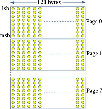
The actual display area is 25mm wide by 14mm high and has 128×64 pixels. Pixels can be white, yellow or black. The display connects to the host microcontroller over an I2C bus which greatly simplifies wiring.
Pixels are mapped to graphics memory as follows:
Each graphics memory byte controls a column of 8 pixels. 128 bytes cover a strip of 128×8 pixels or “a page” as its called in the data sheet. This display has 8 pages giving a resolution of 128×64 pixels. To set a particular pixel, you need to identify which page it is on and which byte and bit connects to it within this page. In theory you could then drive this pixel on or off as desired however there is a problem: graphics memory is written in byte-sized chunks so if you want to set a particular pixel, you need to read the byte connected to it, modify the bit in question and then write it back. Unfortunately, the I2C interface for the SSD1306 does not permit reading of graphics memory.
The Adafruit driver for this display gets around this problem by maintaining a copy of the graphics memory in the host MCU. It then updates the whole display when things change. This consumes a fair amount of RAM in the host MCU (128×8 = 1024 bytes) and is slow as the whole display must be updated if a single pixel changes.
My first attempt at controlling this display takes a different approach. The display is treated as a text only device capable of displaying 25×8 characters. Screen updates are carried out at page level i.e. 128 byte chunks are written at a time which corresponds to a single line of text. An I2C driver buffers this data and outputs to the display on an interrupt driven basis. This greatly reduces RAM consumption and speeds updates.
Programming and debugging
Openocd version 0.10 or later is required for the STM32L031. You may get this ready built for your OS or download the source and compile yourself. In my case, I downloaded the source from openocd.org. This was extracted and compiled as follows (as the root user):
apt-get install libusb-1.0-0-dev
./configure –enable-stlink –enable-maintainer-mode
make
make install
The STM32L031 was connected to the host PC using an ST-Link V2 clone and the debug/programming session was started this:
/usr/local/bin/openocd
-f /usr/local/share/openocd/scripts/interface/stlink-v2.cfg
-f /usr/local/share/openocd/scripts/target/stm32l0.cfg
I previously used a GY-652 module as the basis for a weather station. The module contains a BMP180 pressure/air sensor and a HMC5983 electronic compass. The weather station ran for about 4 months on 3 AAA batteries which was reasonable enough although the GY-652 had an unexpectedly large quiescent current of around 1mA.
Anyway, the batteries needed recharging and I decided it would be interesting to see if the HMC5983 could be useful in such an environmental monitoring test.
The Earth’s magnetic field varies from around 250 mG to about 650 mG. During solar storms, this can vary by as much as 170 milli-Gauss (source: http://www.spaceweather.gc.ca/svr-en.php). Daily variations in the magnetic field are of the order of 0.4 milli-Gauss. Are these measurable by the HMC5983 I wonder? According to its datasheet, the noise floor for the device is 2 mG so that probably rules out the detection of daily field variation. Storms are another matter however and these should be measurable by the device.
Batteries were recharged and code modified to make use of the HMC5983. The base-station for the weather station is now connected to a Raspberry Pi which relays the data up to Thingspeak. I’m going to leave it for a month or as long as the batteries hold out and, who knows, maybe it will spot a solar storm. Click here to view the data on Thingspeak. Update 20 January 2018
After a month or so in operation I think I *may* have seen some correlation between solar activity and magnetic reading variations. There is also some correlation between the magnetic field readings and temperature. The system had been using 3 rechargeable AAA batteries which have been drained twice (need to work on my low power mode :).
To overcome some of these shortcomings I’ve opted to move the sensor out of the attic and placed it under the stairs (unheated area, not too near any big electrical or magnetic fields). I’ve also replaced the AAA batteries with AA ones. Now just have to wait for a big solar storm…
On Saturday the 18th of November Breadboard games version 2 had its first outing in Bunclody library in Wexford. Shannon Chance from the RobosSlam team has documented the day here: https://shannonchance.net/2017/11/19/bread-board-games/
I’ve been trying to program the STM32L432 Nucleo-32 board using the mbed compiler. It has not been working. I can program a range of other boards without any problem. I noticed that the programming LED did not change when I tried to program the device and remembered that I had seen this before. The problem seems to be as follows:
When you load a program on to an MBED enabled Nucleo-32 board the firmware in the loader checks to see if the first 32 bit word (which will form the initial stack pointer) lies within the available RAM on the target. The value output by the mbed compiler for the L432KC is 0x20010000 – the top of the 64kB of RAM. This should be ok (you would think) however it is rejected by the loader. Using a hex editor I changed the first word to 0x2000C000 (the top of a 48 kB block of SRAM1) and it worked.
So, either there is a bug with the mbed linker script and/or initialization files or the loader on the Nucleo board is misinterpreting the available RAM.
Anyway, I’ve posted this as a bug(/fix) to mbed and will see what happens.
Update: There is updated firmware for the STM32L432 Nucleo board over here: http://www.st.com/en/evaluation-tools/nucleo-l432kc.html It fixes this problem and the board accepts an initial stack pointer that lies within SRAM2 now.
A previous post described the building of a weather station based around an STM32F030 and an NRF905 radio. I put 3 freshly charged AAA batteries into the station on August 7th (2017) and more than 10 weeks later, the system is still reporting atmospheric pressure and temperature every minute.
I have been using some SX1278 modules for LoRa experiments. The pin spacing on these modules is 1.27mm – half of the pin spacing found on a breadboard. Interestingly, ribbon cable is exactly the right pitch and I previously managed to solder a length of ribbon cable to a module however, the wiring was prone to fatigue and soon became unreliable. Rummaging around my parts drawer I came across a 24 pin SOP24 to DIP adapter board. This is the sort of board you use with surface mount SSOP chips when you need to work with them on a breadboard. The spacing between pins on the SSOP pins is exactly 1.27mm. These adapter boards are very cheap ( < 10c) and it they can be used with the SX1278 as shown above to make it breadboard compatible
The ultimate intention of this project is to set up a LoRa to TCP/IP gateway. I decided that the ESP32 would make a good bridging device and found one here for about €6. The LoRa transceivers were obtained from Aliexpress also and are available here. Interfacing with the ESP32 was pretty straightforward as the LoRa module simply connects to its SPI interface. The really tricky part was connecting up to the 1/20 inch pitch connector on the LoRa module.
Software
I decided to develop my own LoRa driver module for the ESP32. Its API is based on the equivalent library for Arduino (I felt it would be easier to deal with just one API). Code was developed using the ESP development environment and is available here
Sender
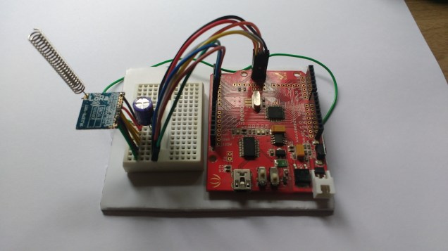
Every conversation needs at least two parties so a device was needed to send some test data to the ESP32 board. A Seeduino was connected to an SX1278 LoRa module as shown here:
The great thing about the Seeduino is that you can switch its I/O to 3.3V which allows you directly connect it to the SX1278 module. The code (which makes use of the Arduino SX1278 library) is as follows:
#include <SPI.h>
#include <LoRa.h>

int counter = 0;

void setup() {
  Serial.begin(9600);
  delay(1000);
  //while (!Serial);

  Serial.println("LoRa Sender");
  // override the default CS, reset, and IRQ pins (optional)
  LoRa.setPins(7, 5, 6); // set CS, reset, IRQ pin


  if (!LoRa.begin(433123000)) {
    Serial.println("Starting LoRa failed!");
    while (1);
  }
  // The following settings should maximize reliability
  LoRa.setTxPower(20); // going beyond 10 is illegal
  LoRa.setSpreadingFactor(12);
  LoRa.setSignalBandwidth(125000);
  LoRa.setCodingRate4(5);
  pinMode(2,OUTPUT);
  Serial.println("Setup done");

}

void loop() {
  Serial.print("Sending packet: ");
  Serial.println(counter);
  digitalWrite(2,HIGH);
  // send packet
  LoRa.beginPacket();
  LoRa.print("hello ");
  LoRa.print(counter);
  LoRa.endPacket();
  digitalWrite(2,LOW);
  counter++;

  delay(4000);
}
Testing
The main performance measure I was concerned with was range as the data sizes were very small. The Arduino end of the radio link used the coiled quarter wavelength antenna supplied with the module. The ESP32 end used a straight quarter wavelength monopole. Range testing consisted of me walking around the neighborhood with the Arduino end in a bag while talking with my sons over the phone while they watched the ESP32 end. The ESP32 “base station” was located inside a house with foil backed insulation (which didn’t help). The testing was carried out in a suburban area with lots of houses, trees, cars and so on.
Results and discussion
The best range I managed to get was 770m (measured on Google maps). I suspect that this can be improved if I switch to dipole antennas and if I locate outside the foil envelope of the house. Watch this space 🙂
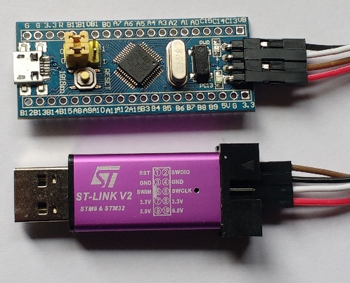
STLink V2 clone debugger: $1.79
MCU breakout board : $1.68
Total : $3.47
Delivery time : 2 weeks
This development kit is based around the stm32f103C8T6MCU. This is a 72MHz Cortex M3 device with 64kB of flash memory and 20kB of RAM. The debugger is an ST-Link V2 clone which can be used to debug STM32 and STM8 devices. I used this with OpenOCD and needed to edit/creaqte the configuration files stm32f103_aliexpress.cfg and stm32f1x_64k.cfg (see below for contents of these files). Note: the register that tells OpenOCD the size of system flash incorrectly indicates 128kB so a value of 64kB is forced in the configuration file. The first test program was blinky of course but this time I decided NOT to write the device header file myself but instead make use of ST Microelectronics
System View Description file (SVD file) for this device. This can be downloaded from here: http://www.st.com/resource/en/svd/stm32f1_svd.zip. Contained in the zip file is STM32F103.svd : an XML description of the peripheral registers within the STM32F103. A separate utility called SVDConv.exe was used to convert this “svd” file to a header file suitable for use with GCC. The SVDConv utility was found in Keil’s ARM MDK (http://www2.keil.com/mdk5/). I’m working in Linux so the conversion command was:
This produced the header file STM32F103.h. The header uses structure definitions and pointers to structures to access peripherals and the registers within them. It also has a couple of dependencies include/core_cm3.h and include/system_ARMCM3.h. I started down the road of finding these only to realise that these too had further dependencies. Furthermore, they served to hide a lot of the startup code, interrupt vectors and so on that I like to keep an eye on. So, there are two choices: either remove the #include statements for the dependencies or create empty files with those names. I did the latter as it left the STM32F103.h file unchanged. An additional header file of my own (cortexm3.h) is needed to fix up a couple of missing symbols which are defined as shown below (other symbols are also defined):
These symbols refer to Input/Output datatypes which should probably always be volatile – in short it works.
As an experiment, I tried using STM32Cube to generate code for a simple blinky project. First of all, I should say that it worked (more or less – I had to manually edit the output Makefile to point to the directory where arm-none-eabi-gcc was installed). This is probably a great tool for a company that is producing a range of products across different members of the ARM-Cortex family. From a teaching and learning perspective though the generated code is of limited use. It is littered with conditional compiles, helper functions that hide important details, and requires you place your code between various sets of comments. The generated code is also MUCH larger than the version below. In short it obscures the lower levels of the microcontroller that I’m interested in teaching. The approach I’ve taken here is to use the device’s SVD file for the peripherals and my own, simpler, device specific Cortex M3 cpu core file. I also used my own simplified initialization code to show exactly what goes on after reset.
Blinky
/* User LED is on PC13 */
#include <stdint.h>
#include "../include/cortexm3.h"
#include "../include/STM32F103.h"
void delay(uint32_t dly)
{
    while(dly--);
}
int main()
{
    // Turn on GPIO C
    RCC->APB2ENR |= BIT4;
    // Configure PC13 as an output
    GPIOC->CRH |= BIT20;
    GPIOC->CRH &= ~(BIT23 | BIT22 | BIT21);
    while(1)
    {
        GPIOC->ODR |= BIT13;
        delay(1000000);
        GPIOC->ODR &= ~BIT13;
        delay(1000000);
    }
}
This is built with a script file (or batch file) that executes the following commands:
The second line of this is not necessary strictly speaking. I use the same script for mbed boards and the “bin” output format is useful there.
Running and debugging
I tried to write out all of the steps in this but decided that a video would be much better. Its over here:
Further examples
A number of other examples are to be found over here https://github.com/fduignan/stm32f103c8t6. These include Systick (at default 8MHz) speed, Systick at 72MHz and UART input/output.
Appendix: OpenOCD configuration files
stm32f103_aliexpress.cfg:
# FILE: stm32f103_aliexpress.cfg
# stm32f103 board and ST-Link v2 from Aliexpress
source [find interface/stlink-v2.cfg]
transport select hla_swd
set WORKAREASIZE 0x2000
source stm32f1x_64k.cfg
reset_config none
stm32f1x_64k.cfg
# FILE: stm32f1x_64k.cfg
# MODIFIED: script for stm32f1x family : forced Flash size to 64kB

#
# stm32 devices support both JTAG and SWD transports.
#
source [find target/swj-dp.tcl]
source [find mem_helper.tcl]

if { [info exists CHIPNAME] } {
   set _CHIPNAME $CHIPNAME
} else {
   set _CHIPNAME stm32f1x
}

set _ENDIAN little

# Work-area is a space in RAM used for flash programming
# By default use 4kB (as found on some STM32F100s)
if { [info exists WORKAREASIZE] } {
   set _WORKAREASIZE $WORKAREASIZE
} else {
   set _WORKAREASIZE 0x1000
}

#jtag scan chain
if { [info exists CPUTAPID] } {
   set _CPUTAPID $CPUTAPID
} else {+
   if { [using_jtag] } {
      # See STM Document RM0008 Section 26.6.3
      set _CPUTAPID 0x3ba00477
   } {
      # this is the SW-DP tap id not the jtag tap id
      set _CPUTAPID 0x1ba01477
   }
}

swj_newdap $_CHIPNAME cpu -irlen 4 -ircapture 0x1 -irmask 0xf -expected-id $_CPUTAPID

if { [info exists BSTAPID] } {
   # FIXME this never gets used to override defaults...
   set _BSTAPID $BSTAPID
} else {
  # See STM Document RM0008
  # Section 29.6.2
  # Low density devices, Rev A
  set _BSTAPID1 0x06412041
  # Medium density devices, Rev A
  set _BSTAPID2 0x06410041
  # Medium density devices, Rev B and Rev Z
  set _BSTAPID3 0x16410041
  set _BSTAPID4 0x06420041
  # High density devices, Rev A
  set _BSTAPID5 0x06414041
  # Connectivity line devices, Rev A and Rev Z
  set _BSTAPID6 0x06418041
  # XL line devices, Rev A
  set _BSTAPID7 0x06430041
  # VL line devices, Rev A and Z In medium-density and high-density value line devices
  set _BSTAPID8 0x06420041
  # VL line devices, Rev A
  set _BSTAPID9 0x06428041
}

if {[using_jtag]} {
 swj_newdap $_CHIPNAME bs -irlen 5 -expected-id $_BSTAPID1 \
	-expected-id $_BSTAPID2 -expected-id $_BSTAPID3 \
	-expected-id $_BSTAPID4 -expected-id $_BSTAPID5 \
	-expected-id $_BSTAPID6 -expected-id $_BSTAPID7 \
	-expected-id $_BSTAPID8 -expected-id $_BSTAPID9
}

set _TARGETNAME $_CHIPNAME.cpu
target create $_TARGETNAME cortex_m -endian $_ENDIAN -chain-position $_TARGETNAME

$_TARGETNAME configure -work-area-phys 0x20000000 -work-area-size $_WORKAREASIZE -work-area-backup 0

# flash size will NOT be probed: Force to 64k (error in chip config register)
set _FLASHNAME $_CHIPNAME.flash
flash bank $_FLASHNAME stm32f1x 0x08000000 0x10000 0 0 $_TARGETNAME

# JTAG speed should be <= F_CPU/6. F_CPU after reset is 8MHz, so use F_JTAG = 1MHz
adapter_khz 1000

adapter_nsrst_delay 100
if {[using_jtag]} {
 jtag_ntrst_delay 100
}

reset_config srst_nogate

if {![using_hla]} {
    # if srst is not fitted use SYSRESETREQ to
    # perform a soft reset
    cortex_m reset_config sysresetreq
}

$_TARGETNAME configure -event examine-end {
	# DBGMCU_CR |= DBG_WWDG_STOP | DBG_IWDG_STOP |
	#              DBG_STANDBY | DBG_STOP | DBG_SLEEP
	mmw 0xE0042004 0x00000307 0
}

$_TARGETNAME configure -event trace-config {
	# Set TRACE_IOEN; TRACE_MODE is set to async; when using sync
	# change this value accordingly to configure trace pins
	# assignment
	mmw 0xE0042004 0x00000020 0
}