I wanted to continue my investigation of the Microbit V2 and Zephyr by adding an external I2C device. The BMP280 module I chose is able to report back temperature and atmospheric pressure. I thought it would be nice to combine this with the earlier ST7789 example to produce a live reading of temperature and pressure on the display. This required a slight modification to the ST7789 setup as it is not possible to use both I2C1 and SPI1 in the same NRF52833 (microbit) project. This was easily fixed as the NRF52833 has SPI interfaces 0 to 2. I chose SPI1 which led me to write the following app.overlay file:
&spi2 {
 compatible = "nordic,nrf-spi";
 status = "okay";
 sck-pin = <17>;
 mosi-pin = <13>;
 /* Redirecting MISO to a pin that is not connected on the microbit v2 board */
 miso-pin = <27>;
 clock-frequency = <1000000>;
};
&i2c1 {
	compatible = "nordic,nrf-twim";
	status = "okay";
	sda-pin = < 0x20 >; // P1.0 = pin reference 32+0 = I2c_EXT_SDA
	scl-pin = < 0x1a >; // P0.26 = pin reference 0x1a = I2C_EXT_SCL
};
I wanted to learn about using an external SPI device with the BBC Microbit V2. I ported my ST7789 library over to a Zephyr based program shown running on the Microbit and it is shown in operation above. The SPI interface runs at a fairly slow 8MHz which I believe (for now) is the maximum for this interface. As a result, screen updates are not super quick but probably good enough for a simple user interface.
The display library supports the following functions:
I was in touch with the Zephyr developers about a bug in the driver for the magnetometer used on the BBC microbit. They kindly fixed it and I have modified my previous magnetometer example. I have also been working on a stripped down BLE example which provides a single service with a single Read/Write/Notify characteristic. The original zephyr set of examples has a very good but also quite complex BLE example. The example makes use of lots of macros that construct various structures and arrays. These can be a little daunting for a beginner. I have tried to remove anything that is non-essential for this example and have added additional comments and references to header files and web resources that will hopefully explain what is going on a little better.
The listing for main.c is shown below. The full set of examples is over here on github. Feel free to post questions in the comments section.
/* main.c - Application main entry point */

/* Based on an example from Zephyr toolkit, modified by frank duignan
 * Copyright (c) 2015-2016 Intel Corporation
 *
 * SPDX-License-Identifier: Apache-2.0
 */
/* This example advertises three services:
 * 0x1800 Generic ACCESS (GAP)
 * 0x1801 Generic Attribute (GATT - this is part of the software device and is not used nor is it apparently removable see https://devzone.nordicsemi.com/f/nordic-q-a/15076/removing-the-generic-attribute-0x1801-primary-service-if-the-service-changed-characteristic-is-not-present
 * And a custom service 1-2-3-4-0
 * This custom service contains a custom characteristic called char_value
 */
#include <zephyr/types.h>
#include <stddef.h>
#include <string.h>
#include <errno.h>
#include <sys/printk.h>
#include <sys/byteorder.h>
#include <zephyr.h>

#include <settings/settings.h>

#include <bluetooth/bluetooth.h>
#include <bluetooth/hci.h>
#include <bluetooth/conn.h>
#include <bluetooth/uuid.h>
#include <bluetooth/gatt.h>
#include <device.h>
#include <drivers/sensor.h>
#include <stdio.h>


#define BT_UUID_CUSTOM_SERVICE_VAL BT_UUID_128_ENCODE(1, 2, 3, 4, (uint64_t)0)
static struct bt_uuid_128 my_service_uuid = BT_UUID_INIT_128( BT_UUID_CUSTOM_SERVICE_VAL);
static struct bt_uuid_128 char_id=BT_UUID_INIT_128(BT_UUID_128_ENCODE(1, 2, 3, 4, (uint64_t)5)); // the 128 bit UUID for this gatt value
uint32_t char_value; // the gatt characateristic value that is being shared over BLE
static ssize_t read_char(struct bt_conn *conn, const struct bt_gatt_attr *attr, void *buf, uint16_t len, uint16_t offset);
static ssize_t write_char(struct bt_conn *conn, const struct bt_gatt_attr *attr, const void *buf, uint16_t len, uint16_t offset, uint8_t flags);

/* The bt_data structure type:
 * {
 * 	uint8_t type : The kind of data encoded in the following structure
 * 	uint8_t data_len : the length of the data encoded
 * 	const uint8_t *data : a pointer to the data
 * }
 * This is used for encoding advertising data
*/
/* The BT_DATA_BYTES macro
 * #define BT_DATA_BYTES(_type, _bytes...) BT_DATA(_type, ((uint8_t []) { _bytes }), sizeof((uint8_t []) { _bytes }))
 * #define BT_DATA(_type, _data, _data_len) \
 *       { \
 *               .type = (_type), \
 *               .data_len = (_data_len), \
 *               .data = (const uint8_t *)(_data), \
 *       }
 * BT_DATA_UUID16_ALL : value indicates that all UUID's are listed in the advertising packet
*/
// bt_data is an array of data structures used in advertising. Each data structure is formatted as described above
static const struct bt_data ad[] = {
	BT_DATA_BYTES(BT_DATA_FLAGS, (BT_LE_AD_GENERAL | BT_LE_AD_NO_BREDR)), /* specify BLE advertising flags = discoverable, BR/EDR not supported (BLE only) */
	BT_DATA_BYTES(BT_DATA_UUID128_ALL, BT_UUID_CUSTOM_SERVICE_VAL /* A 128 Service UUID for the our custom service follows */),
};

/*
 * #define BT_GATT_CHARACTERISTIC(_uuid, _props, _perm, _read, _write, _value)
 *
 */
BT_GATT_SERVICE_DEFINE(my_service_svc,
	BT_GATT_PRIMARY_SERVICE(&my_service_uuid),
		BT_GATT_CHARACTERISTIC(&char_id.uuid,
		BT_GATT_CHRC_READ | BT_GATT_CHRC_WRITE |  BT_GATT_CHRC_NOTIFY,
		BT_GATT_PERM_READ | BT_GATT_PERM_WRITE,
		read_char, write_char, &char_value),
);


struct bt_conn *active_conn=NULL; // use this to maintain a reference to the connection with the central device (if any)


// Callback that is activated when the characteristic is read by central
static ssize_t read_char(struct bt_conn *conn, const struct bt_gatt_attr *attr, void *buf, uint16_t len, uint16_t offset)
{
	printf("Got a read %p\n",attr);
	// Could use 'const char *value =  attr->user_data' also here if there is the char value is being maintained with the BLE STACK
	const char *value = (const char *)&char_value; // point at the value in memory
	return bt_gatt_attr_read(conn, attr, buf, len, offset, value, sizeof(char_value)); // pass the value back up through the BLE stack
}
// Callback that is activated when the characteristic is written by central
static ssize_t write_char(struct bt_conn *conn, const struct bt_gatt_attr *attr,
			 const void *buf, uint16_t len, uint16_t offset,
			 uint8_t flags)
{
	uint8_t *value = attr->user_data;
	printf("Got a write\n");
	memcpy(value, buf, len); // copy the incoming value in the memory occupied by our characateristic variable
	return len;
}
// Callback that is activated when a connection with a central device is established
static void connected(struct bt_conn *conn, uint8_t err)
{
	if (err) {
		printk("Connection failed (err 0x%02x)\n", err);
	} else {
		printk("Connected\n");
		active_conn = conn;
	}
}
// Callback that is activated when a connection with a central device is taken down
static void disconnected(struct bt_conn *conn, uint8_t reason)
{
	printk("Disconnected (reason 0x%02x)\n", reason);
	active_conn = NULL;
}
// structure used to pass connection callback handlers to the BLE stack
static struct bt_conn_cb conn_callbacks = {
	.connected = connected,
	.disconnected = disconnected,
};
// This is called when the BLE stack has finished initializing
static void bt_ready(void)
{
	int err;
	printk("Bluetooth initialized\n");

// start advertising see https://developer.nordicsemi.com/nRF_Connect_SDK/doc/latest/zephyr/reference/bluetooth/gap.html
/*
 * Excerpt from zephyr/include/bluetooth/bluetooth.h

 * #define BT_LE_ADV_CONN_NAME BT_LE_ADV_PARAM(BT_LE_ADV_OPT_CONNECTABLE | \
                                            BT_LE_ADV_OPT_USE_NAME, \
                                            BT_GAP_ADV_FAST_INT_MIN_2, \
                                            BT_GAP_ADV_FAST_INT_MAX_2, NULL)

 Also see : zephyr/include/bluetooth/gap.h for BT_GAP_ADV.... These set the advertising interval to between 100 and 150ms

 */
// Start BLE advertising using the ad array defined above
	err = bt_le_adv_start(BT_LE_ADV_CONN_NAME, ad, ARRAY_SIZE(ad), NULL, 0);
	if (err) {
		printk("Advertising failed to start (err %d)\n", err);
		return;
	}
	printk("Advertising successfully started\n");
}

void main(void)
{
	int err;

	err = bt_enable(NULL);
	if (err) {
		printk("Bluetooth init failed (err %d)\n", err);
		return;
	}

	bt_ready();
	bt_conn_cb_register(&conn_callbacks);
	printk("Zephyr Microbit V2 minimal BLE example! %s\n", CONFIG_BOARD);
	while (1) {
		k_sleep(K_SECONDS(1));
		char_value++;
		// int bt_gatt_notify(struct bt_conn *conn, const struct bt_gatt_attr *attr, const void *data, u16_t len)
		// conn: Connection object. (NULL for all)
		// attr: Characteristic Value Descriptor attribute.
		// data: Pointer to Attribute data.
		// len: Attribute value length.
		if (active_conn)
		{
			bt_gatt_notify(active_conn,&my_service_svc.attrs[2], &char_value,sizeof(char_value));
		}
	}
}
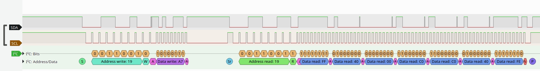
The BBC Microbit V2’s I2C interface usage is different to it’s predecessor. It has two I2C interfaces : an internal one to talk to the on-board accelerometer/magnetometer and an external one for user supplied sensors. Traffic on the internal I2C bus is only visible on tespoints (TP20 and TP21). This makes it difficult to debug/view the internal I2C bus traffic. I had no springloaded test pins to press on to the testpoints so a quick hack as shown above provides just enough pressure on the pads to make an electrical connection. The orange and purple wires are coiled like a spring which causes them to press into the board. These wires are then connected to a logic analyzer via the breadboard. The analyzer displays the following data:
The I2C clock frequency seems to be 400kHz. There appears to be some kind of clock stretching going on also. The trace shows a read from the on-board accelerometer.
In previous years I used mbed OS to program the BBC Microbit (V1). As far as I can tell, the V2 board is not supported in mbed’s web compiler (yet?). So I began to look around at alternatives operating systems that would help me develop BLE peripheral applications. I considered install size and system requirements and decided that Zephyr looked like a good fit. I have begun writing examples for the various peripherals on the microbit v2 source code for which is over on github.
You will need to install zephyr to compile these. I found that the Getting started guide worked well. I compile my examples within the zephyrproject/zephyr directory (copy them from github to here) with the following command:
west build -b bbc_microbit_v2 magnetometer_serial_microbit_v2 –pristine
This will wipe the build directory and recompile the magnetometer example. Change “magnetometer_serial_microbit_v2” to one of the other directory names when you want to try them out. The output from the application on the microbit is sent to UART at 115200 bps.
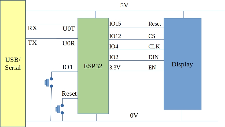
I got hold of a Vacuum Fluorescent Display module from Aliexpress. It comes in two versions : one with an SPI interface, one without. I went with the SPI interface version. The display reminded me of a clock radio I had growing up so it was natural to put it to work as a clock. I wired it to an ESP32-CAM module as shown below:
Details about how the display is programmed were found over here. I wanted to use the SPI hardware interface instead of bit-banging the data and so developed the following program using Arduino for ESP32:
#include <SPI.h>
#include <WiFi.h>
#include <NTPClient.h>
#include <HTTPClient.h>

/*
  ESP32 based clock.
  Uses Vacuum Fluourescent Display (VFD)
  Gets time from an NTP server
*/

WiFiUDP ntpUDP;
NTPClient timeClient(ntpUDP);

const char* ssid = "***********";
const char* password =  "****************";

class VFDisplay
{
  public:
    VFDisplay() {};
  void begin()
  {
    SPI.begin(SCK,MISO,MOSI,SS);
    pinMode(Reset,OUTPUT);
    pinMode(CS,OUTPUT);
    digitalWrite(Reset, LOW);
    delayMicroseconds(5);
    digitalWrite(Reset, HIGH);

    setDigitCount(8);
    setBrightness(127);
    Serial.printf("VFD_init\n");
  }
  void putChar(unsigned char x, char chr)
  {
    digitalWrite(CS, LOW);
    writeDisplay(0x20 + x);
    writeDisplay(chr);
    digitalWrite(CS, HIGH);
    show();
  }
  void printString(char *str)
  {
    int x = 0;
    while(*str)
    {
      putChar(x++,*str++);
    }
  }
  private:
  void setDigitCount(uint8_t count)
  {
      digitalWrite(CS, LOW);
      writeDisplay(0xe0);
      delayMicroseconds(5);
      writeDisplay(count-1);
      digitalWrite(CS, HIGH);
      delayMicroseconds(5);
  }
  void setBrightness(uint8_t brightness)
  {
    digitalWrite(CS, LOW);
    writeDisplay(0xe4);
    delayMicroseconds(5);
    writeDisplay(brightness);
    digitalWrite(CS, HIGH);
    delayMicroseconds(5);
  }
  void show()
  {
    digitalWrite(CS, LOW);
    writeDisplay(0xe8);
    digitalWrite(CS, HIGH);
  }
  void writeDisplay(uint8_t b)
  {
    SPI.beginTransaction(SPISettings(1000000, LSBFIRST, SPI_MODE0));
    SPI.write(b);
    SPI.endTransaction();
  }

  uint8_t Reset=15;
  uint8_t CS = 12;
  uint8_t SCK = 4;
  uint8_t MOSI = 2;
  uint8_t MISO = 1;
  uint8_t SS = 12; // not actually used - see CS above

};

VFDisplay vfdisplay;
void setup() {

  Serial.begin(115200);
  vfdisplay.begin();
  WiFi.begin(ssid, password);
  while (WiFi.status() != WL_CONNECTED) {
    vfdisplay.printString("WifiWait");
    delay(1000);
  }
  vfdisplay.printString("WifiDone");
  timeClient.begin();
  timeClient.setTimeOffset(3600);
  timeClient.update();
  timeClient.setUpdateInterval(5*60*1000); // update from NTP only every 5 minutes
}

void loop() {
  timeClient.update();     // This will only go to the Internat if the update interval has passed (set to 5 minutes above)
  String timeString = timeClient.getFormattedTime();
  char TimeCharArray[20];
  timeString.toCharArray(TimeCharArray,19);
  vfdisplay.printString(TimeCharArray);
  delay(100);
}
The system appears to work well and could be extended to include a Bluetooth interface to set an alarm time or time zone etc.
Renesas produce an ARM Cortex M23 based microcontroller called the R7FA2A1AB3CFJ or RA2A1. This device has 256k of flash memory and 32k of RAM. It also has a number of peripherals and memory/security mechanisms. I was interested in learning about the device at a low level and so I did not use the extensive libraries and support files available from Renesas. Instead I decided to write my own device header file and linker and build scripts.
The breadboard circuit
The schematic and photograph of the breadboard kit are shown above. The RA2A1 chosen is housed in a 32 pin LQFP package and was broken out into a DIL arrangement using an adapter.
Option words
The post-reset state of the RA2A1 is configured using some option words that are located within the system flash memory. It is important that you avoid accidentally overwriting these bytes when writing your program to flash memory. The option setting memory words are at:0x400 and 0x404 i.e. 0x400-0x407 inclusive. I modified my usual linker script so that the program flash area starts after the option memory (with a little margin). The interrupt vectors must still be stored at address zero so a memory regision called “vector_area” is defined as shown. The linker will only position the interrupt vector table there.
When I started using this chip I accidentally overwrote the option memory and was left with a non-functioning chip. The support people in Renesas helped and provided a script that you can use to erase the lower parts of flash back to factory defaults. Details are here:
The RA2A has a total of 32 interrupt vectors (beyond the 16 internal ARM Cortex ones). These interrupt vectors are mapped to peripheral events using 32 Event Link Setting Registers in the Interrupt Control Unit (one ELSR per interrupt vector). The ELSR’s allow you associate an event number with an interrupt vector. Each peripheral has one or more event numbers associated with it e.g. The Receive event for Serial Communications Interface 0 is event number 0x71. In the examples below, this is associated with interrupt vector 0 as follows:
ICU_IELSR[0] = 0x71;
When a byte is received by SCI0 the first (non-ARM) interrupt vector is fetched and the handler at that address is exectuted.
Pin Function Selection
Like most microcontrollers, the RA2A1 allows you assign pins to a selection of peripherals. The RA2A1 handles this by using a 16 word array for each port (there are 5 ports each with 16 bits). Each of these array elements allows you set pin direction, peripheral function, interrupt mode, pull-ups etc. The user manual provides a table with the peripherals that can be mapped to each I/O pin. There is a protection mechanism associated with the pin function selection system (as well as other systems). This requires writes to a couple of registers to unlock.
The SDADC24
The RA2A1 has a 24 bit Sigma Delta ADC which includes an instrumentation amplifier with a programmable gain and an offset adjustment system. This is potentially very interesting for instrumentation applications. The SDADC is also capable of averaging a number of input samples which reduces noise at the expense of frequency response. It is also possible to control the oversampling of the sigma delta adc to allow for further noise reduction. Included in the examples below is a program which sends the SDADC conversion result out over the SCI0 serial port.
The STM32G431 has a Filter Math ACellerator (FMAC) hardware unit inside of it. This unit can take be used to implement an FIR or IIR filter without burdening the CPU. The FMAC unit has input and output circular buffers as well as a coefficient buffer. It is possible to connect the input buffer to an ADC using DMA and similarly it is possible to connect an output buffer directly to a DAC over DMA. In the case of this project I used an ADC interrupt handler to manage data input and output to the FMAC.
There are lots of tools to help you design a digital filter. I chose to use python and jupyter notebook in this case. The jupyter notebook code is as follows (it is also on the github site linked below)
import numpy as np
import scipy as sp
import scipy.signal as sg
import matplotlib.pyplot as plt
Fs=48000
Fpass=1000
Order=16
Wp=Fpass/(Fs/2)
b=sg.firwin(Order+1,Wp,window = "hamming",pass_zero = True)
w,h=sg.freqz(b)
mag=20*np.log10(abs(h))
plt.figure()
plt.semilogx(w*(Fs/(2*np.pi)), mag)
plt.show()
bmax=np.max(np.abs(b))
# Working out the scale factor can be a bit tricky.  There is a
# 24 bit accumulator in the FMAC.  The ADC has a 12bit range.
# This leaves 12 bits for coefficients if overflows are to be prevented.
# Furthermore, the multiply and accumulate nature of the FIR will push
# results beyond 24 bits if we are not careful.  This is more pronounced with
# lower cut-off frequencies where there is a large central lobe to the filter
# coefficients which may lead to overflows, particularly at low input
# frequencies.  For now I'm just doing this by trial and error
ScaleFactor=4095/(bmax)
f = open('coffs.h', 'w')
f.write("#include <stdint.h>\n")
f.write("#define SCALE_FACTOR ")
f.write(str(int(np.round(ScaleFactor))))
f.write("\n")
f.write("#define FILTER_LENGTH ")
f.write(str(Order))
f.write("\n")
f.write("const int16_t b[]={")
for coeff in b:
    f.write(str(int(np.round(coeff*ScaleFactor))))
    f.write(",\n")
f.write("};\n")

f.close();
plt.figure();
plt.plot(b);
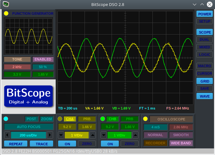
This code outputs a header file that includes the filter coefficients for a low pass FIR filter with a cutoff frequency of 1000Hz. The output at 2kHz is shown below
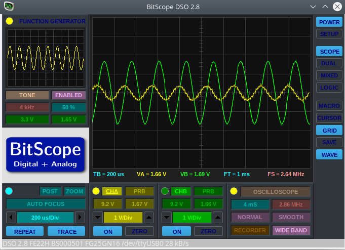
And it 4kHz this becomes:
It would appear that the filter is indeed working however there are a number of caveats. The FMAC uses fixed point arithmetic so coefficients and input signals must be shifted and scaled appropriately. The FMAC has a limited numeric range (24 bits of fractional data internally, 15 bits input and output) and overflows will happen. This is a particular problem at low frequencies with filters whose coefficients are mostly/all positive. I had to do some manual tweaking of the coefficients to get the output performance I wanted. When testing for such overflows it is useful to input a DC signal of maximum voltage to ensure that no overflows occur.
An earlier blog post showed multi-threading on the TI MSP432. Recently I have been working on an STM32L031 Nucleo board with the Keil ARM-MDK environment. I wanted to demonstrate multi-threading and so ported the code from the MSP432 to the L031. A section of the main.c file looks like this:
#define STACK_SIZE 128
__attribute__((noreturn))  void threadA(void);
__attribute__((noreturn)) void threadB(void);
__attribute__((noreturn)) void threadC(void);
static uint32_t StackA[STACK_SIZE];
static uint32_t StackB[STACK_SIZE];
static uint32_t StackC[STACK_SIZE];

void threadA()
{
	while (1)
	{
		static int State = 0;
		if (State == 0)
		{
			GPIOA->ODR &=~(1u << 0);
			State = 1;
		}
		else
		{
			GPIOA->ODR |= (1 << 0);
			State = 0;
		}
		delay(100000);
	}
}
int main()
{
	// Initialize I/O ports
	RCC->IOPENR = 1; // Enable GPIOA
	pinMode(GPIOA,0,1); // Make GPIOA Bit 0 an output
	pinMode(GPIOA,1,1); // Make GPIOA Bit 1 an output
	pinMode(GPIOA,2,1); // Make GPIOA Bit 2 an output
	initClock();		// Set the MCU running at 16MHz
	createThread(threadA,StackA, STACK_SIZE);
	createThread(threadB,StackB, STACK_SIZE);
	createThread(threadC,StackC, STACK_SIZE);
	startSwitcher();
}
Three threads are created in this example and they each change the state of a bit on Port A. I should have used the BSRR register to set and clear the bits but for the purposes of getting the ideas behind multi-threading across this was sufficient. The createThread function takes three arguments: The thread’s start address, a pointer to the thread’s stack and the size of this stack. Stacks for the threads are simply declared as arrays of uint32_t’s.
The startSwitcher function starts the SysTick timer running, does some stack adjustments and enables interrupts. It does not return. The SysTick handler is written in assembler and it performs the context switch between threads.
Source code is available on github. I did not include the project (uvproj) files as they contain lots of path information that would not transfer to other systems. If you want to try this for yourself just create a project for the STM32L031 Nucleo in Keil and add the files from github. You should first remove the other source files in your project.
Given the pandemic restrictions this year Breadboard Games will be delivered remotely. Participants will each receive a kit and work with a parent to assemble the gaming console. Remote support will be provided via video.
Instructions
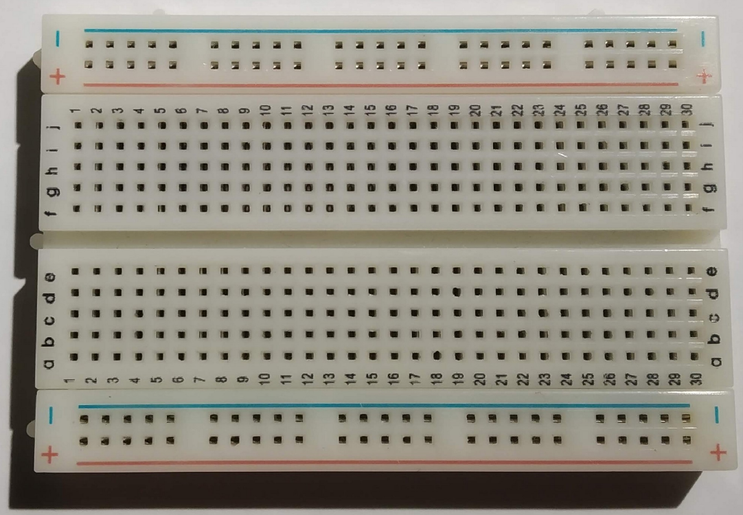
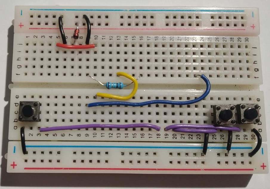
This is a breadboard. It allows us to connect electronic components together by pushing them into the holes. In the centre region all the holes in column 1 are connected together inside the board apart from the gap in the middle. Columns 2 to 30 work similarly. You can see more about breadboards at this location
In the outer, between the blue and red lines, connections run horizontally within the breadboard. We usually use these areas to connect power supplies for our electronic components.
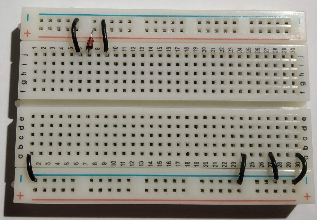
Lets begin by putting the black wires into the board as shown above. The top row of holes next to the blue line will be used to distribute the 0V connections for our circuit (the negative terminal on our battery). The connections are expressed in Row,Column terms as follows:
j6 to 0V (approximately directly above just next to the blue line) j9 to 0V a1 to 0V a24 to 0V a27 to 0V a30 to 0V
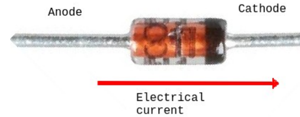
A diode only allows electricity to flow in one direction. We include one here to protect our game in case somebody connects the battery pack in backwards. The diode has two wires : Cathode and Anode.
We want electrical current to flow into hole j7 so put the cathode in there and the anode just above the red line as shown.
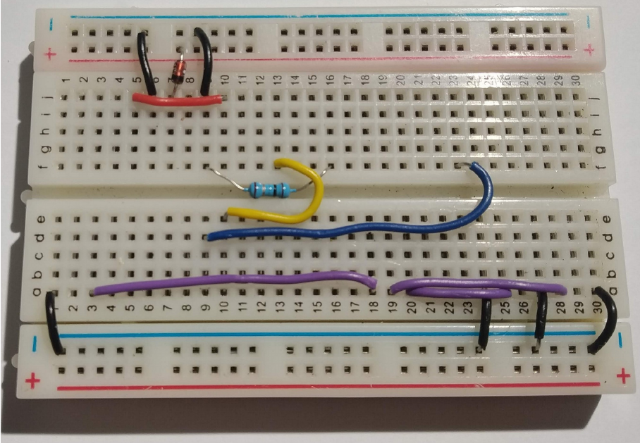
Connect the red wire between j5 and j10. The other component is a resistor. Resistors control the flow of electrical current. We are using this one to limit the brightness of our display so that the batteries last longer. The resistor connections between f9 and f16. Note the way the resistor sits in the valley between both halves of the breadboard.
The screen in our game is a “touch-screen”, just like a phone. We have to add a couple of wires to support this. The yellow wire goes from e10 to f13. The blue wire goes from d9 to f23
The purple wires are used to connect the buttons to the little computer in our game. They are connected as follows: a3 to a18 a19 to a28 a20 to a25
The buttons go in next. Each button has two “pins” that are connected together electrically when you push down. The left button we will call simply “Left”, the rightmost button we will call “Right” and the middle buttonw we will call “Fire”. The connections are as follows: Left: c1 and c3 Fire: c25 and c27 Right : c28 and c30
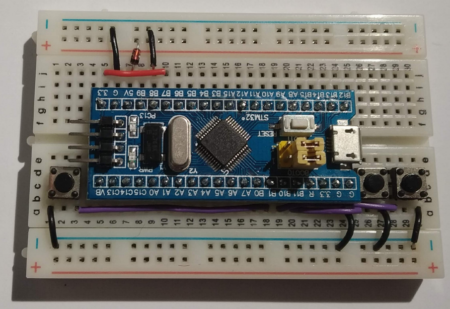
We are nearly done. The computer board that controls our game needs to go in next. Before you put it in be sure that all of the previous connections are correct. It is difficult to remove the computer boards if you need to correct any errors. Push the board firmly into the breadboard with the pin marked “3.3” (top left) in hole g5.
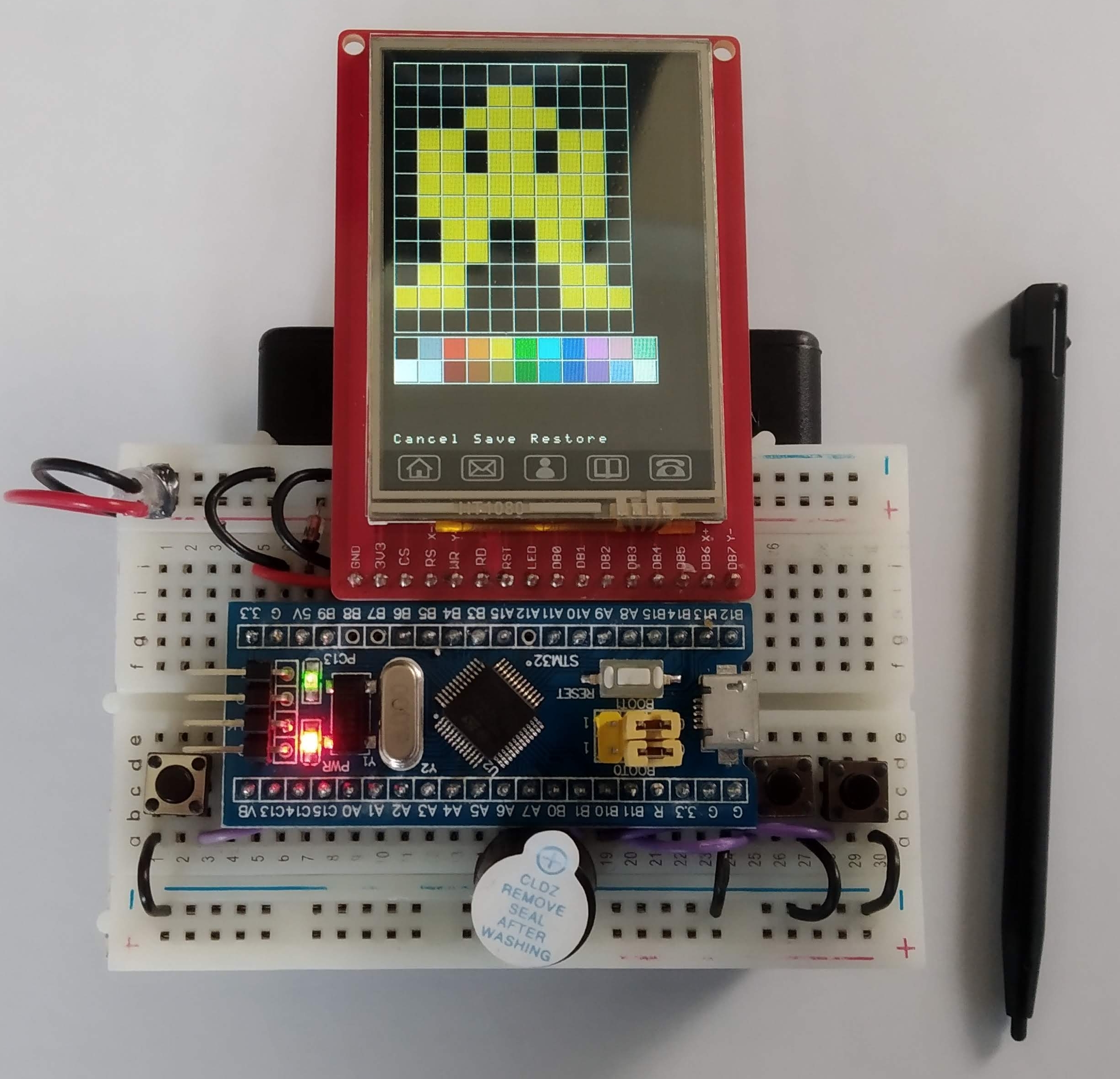
And now for the screen. Be very careful putting this in. It goes in row i. The rightmost pin of the display goes into hole i24. Push down on the pins only, not the glass. The glass will crack if you push on it.
Our game makes sounds. The buzzer is connected between a17 and 0V (just below the blue line). The longer leg of the buzzer (labelled +) goes in to a17.
The battery pack plugs into the board as shown above. Note the red wire is closest to the red line on the breadboard. The on/off switch should be just behind the display on the right hand side. If you like you can stick the breadboard to the battery pack using the adhesive backing on the breadboard. If you decide to do this be very careful as the adhesive backing is very strong.