
The BBC Microbit V2’s I2C interface usage is different to it’s predecessor. It has two I2C interfaces : an internal one to talk to the on-board accelerometer/magnetometer and an external one for user supplied sensors. Traffic on the internal I2C bus is only visible on tespoints (TP20 and TP21). This makes it difficult to debug/view the internal I2C bus traffic. I had no springloaded test pins to press on to the testpoints so a quick hack as shown above provides just enough pressure on the pads to make an electrical connection. The orange and purple wires are coiled like a spring which causes them to press into the board. These wires are then connected to a logic analyzer via the breadboard. The analyzer displays the following data:
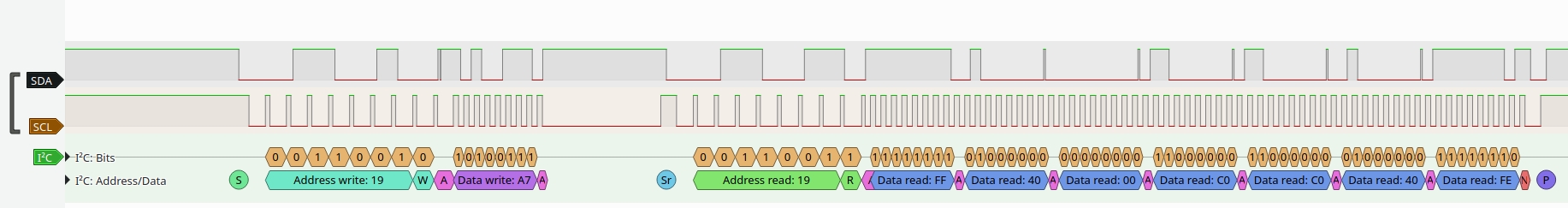
The I2C clock frequency seems to be 400kHz. There appears to be some kind of clock stretching going on also. The trace shows a read from the on-board accelerometer.

Nicely done! Do you have a general map of the test points on the V2 board? Preferably both the exposed ones and the ones helpfully covered with black solder mask.
LikeLike
I found the map of test points here : https://tech.microbit.org/hardware/schematic/#test-point-map
LikeLike