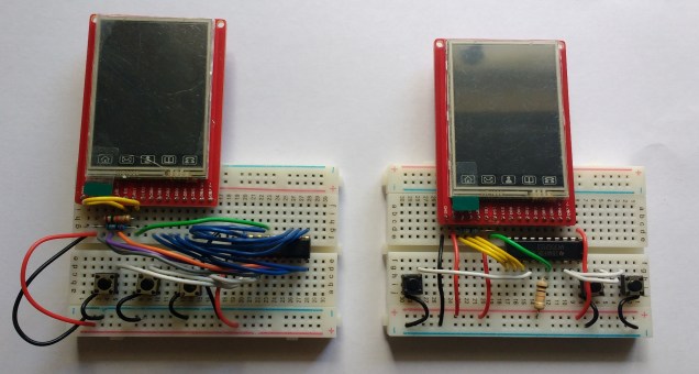
The image above shows two implementations of the same gaming system (ArcadeSlam). The display has a parallel data interface and the left hand version maps this interface to the 8 bits of a single I/O port on the MSP430 MCU. A simple write to the port data register is sufficient to write a byte to the display. From a programming perspective this is easy but, as you can see, the wiring is a little complex.
The version on the right makes use of the connections within the breadboard to connect the display data interface to the MSP430. This greatly simplifies the wiring however it pushes this complexity back into the code. The wiring looks like this:
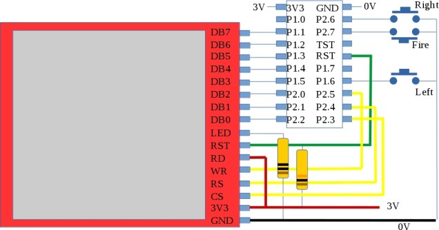
The display data interface is spread across Ports 1 and 2. Not only that, the bits are in reverse order. Reversing bits at run-time represents a performance hit so, a lookup table was generated and the writing of the data bytes goes from this (for the left hand version)
P2OUT = data;
to
P1OUT &=0xc1;
P2OUT &=0xf8;
if (b)
{ // only write out bits if b is non zero to save time
P1OUT |= reverse_bits[ (b >> 3) ] >> 2;
P2OUT |= reverse_bits[ (b & 0x7) ] >> 5;
}
The lookup table reverse_bits was produced using the following python script (only a 5 bit table was necessary)
#!/usr/bin/python
# Output the specified range of numbers with their
# bits reversed as a lookup table suitable for C
print "const uint8_t reverse_bits[]={ \\"
for n in range(32):
print int('{:08b}'.format(n)[::-1], 2),",\\"
print "};"
Performance is not obviously affected by this wiring change and full code can be downloaded over here on github.
More information can also be found on roboslam.com
