I bought a TinyRTC module on dx.com for a couple of euro. It contains an at24c32 32k flash memory IC and a ds1307 real time clock IC. The pictures below show how it was interfaced (via I2C) to an LPC1114FN28. The LPC1114 was programmed using ISP/IAP over a USB to serial interface. GCC 5.2.1 was used to compile code and LPC21ISP was used to download it.

Top view of TinyRTC module on breadboard
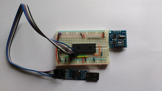
Bottom view of Tiny RTC on breadboard.
The code to drive all of this is available on this github page
The code consists of the following modules:
init : This contains the interrupt vector table and a startup routine which initializes global and static variables, bumps the clock speed up to 48MHz and finally calls on main.
serial : This module manages the UART interface and is used extensively to output run time and debugging information
i2c : This module manages the I2C interface and is implemented as recommended in the LPC1114 reference manual . The I2C interface is implemented as a state machine in hardware and takes a little getting used to. If you enable debugging (uncomment the line #define DEBUG 1 at the start of the i2c.c file) the module outputs debug trace data showing all of the states visited by the I2C state machine.
ds1307: This manages the interface to the RTC and has set/get date routines.
at24c32: This manages the interface with the AT24C32 memory IC and contains functions to read and write random data (be careful of the 1 million write cycles).
main: This is the top level application which exchanges data with the DS1307 and AT24C32.
The DS1307 is capable of outputting a 1Hz square wave which may be used to wake a slumbering MCU from a power saving deep sleep. Hopefully I will get around to this in a future post.
