This post follows up on the previous one and includes a description of the software involved in MCU Invaders. Initially this project started out as a C++ project however I found it difficult to get the initialization “glue” sorted out. It seems that C++ initialization procedures have changes since GCC 4.7 and I didn’t want to get diverted from the main goal figuring this out. It was easier instead to convert to a C project while retaining the object oriented nature in spirit.
The project is made up of the following layers:
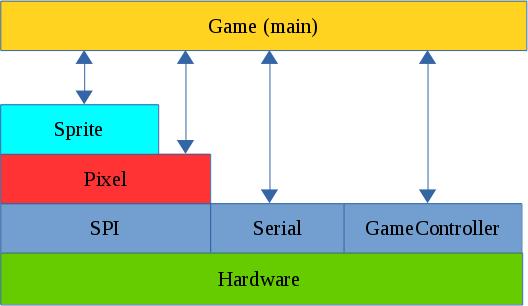
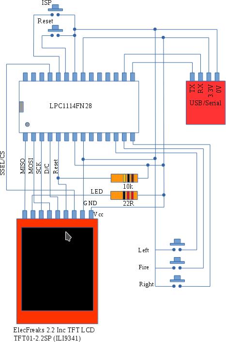
The SPI Layer
Communication with the ILI9341 display is carried out over the SPI bus. This consists of 4 signals:
MOSI (Master Out Slave In). This carries data from the LPC1114 to the ILI9341
MISO (Master In Slave Out). This carries data from the ILI9341 to the LPC1114
SCK (Serial ClocK). This is driven by the master and sets the pace for SPI Communications.
CSn or SSEL. This line is driven by the LPC1114 and can be used to wake up the ILI9341 by driving it low. The LPC1114 is capable of generating this signal automatically when transfers are taking place. This proved to be a problem in this case. The ILI9341 is slow to respond to changes to this signal and this limited data rates to less than 1 Mbit/s. This was not sufficient for the game. I noticed however that if the SSEL (CS) line is kept low all of the time the SPI bus could be run at about 24MHz. This of course means that the SPI bus is dedicated to this display which is not a problem in this case.
The Pixel Layer
This layer “understands” how to control the ILI9341. It is used to initialize the display and contains the following low level graphical functions:
putPixel
putImage
fillRectangle
putText
It also contains the macro RGBToWord which converts RGB colour values (1 byte per colour) into a 16 bit number that can be used by the ILI9341.
The Sprite Layer
typedef struct {
// Location of top left corner.
 uint16_t x;
 uint16_t y;
// Dimensions of sprite
 uint16_t width;
 uint16_t height;
// The pixels for the sprite are stored at this location
 const uint16_t *SpriteImage;
 uint8_t visible;
} Sprite;
// Construction based on 2 D pixel array
void initSprite(Sprite * sp,const uint16_t * InitArray, uint8_t Width, uint8_t Height, uint16_t x, uint16_t y);
// Show/hide the sprite
void showSprite(Sprite * sp); // Put a sprite on the display
void hideSprite(Sprite * sp); // hide the sprite
void drawSprite(Sprite * sp); // show the sprite
// Move to the specified position
void moveSprite(Sprite * sp,uint16_t x, uint16_t y); // move sprite
// Does the sprite contain the given point
uint8_t withinSprite(Sprite * sp,uint16_t x, uint16_t y);
This layer is all about Sprites : Movable pictures on the display. A sprite is defined by a data structure that specifies location, dimensions and a pointer to an array of data that contains the actual image. The remaining functions are used to show/hide and move the sprite. An additional function ‘withinSprite’ is used to test whether a given point is within the sprite. This is used to detect whether missiles or invaders have hit a target.
The game layer (main)
This layer contains all of the game logic. It also defines the shape of the various sprites used. This layer also makes calls out to the serial Communications layer allowing the developer to debug game play. Dynamic memory allocation (new/malloc etc) is not used in this project. Fixed length arrays are used for the invaders and missiles and these are enabled/disabled as necessary. One implication of this is that there can be up to 5 missiles in flight at any one time. There is still sufficient RAM available to increase this number should a developer wish to.
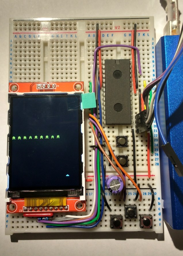
The video below shows the game in operation.
Code is available here on Github