DMB2022 (Dublin Maker Badge for 2022 (not official)) is an electronic badge consisting of an NRF52833 module and a display. The display for the badge is an ST7789 module. It has an SPI interface that is operated at 32MHz. It is configured to use 16 bit RGB colour values arranged as follows:
5 most significant bits : Red
6 middle bits : Green
5 least significant bits : Blue
The NRF52833’s SPI3 is used to drive the display as SPI0 and SPI1 are limited to 8Mbs. SPI3 can operate up to 32Mbs.
The display.cpp module handles all interaction with the ST7789. Lots of LCD displays of this type have a similar pattern of operations.
At startup, the display is first configured which typically involves bringing the device out of low power mode and configuring its colour mode, orientation and optionally its colour palette. The initialization code achieves this by sending commands and data to the display. The D/C signal tells the display whether a command or data byte is being transmitted. If it is Low then a command is being sent; a High level implies data is being sent.
In order to put pixels on the display, the controlling program must first open up an aperture for drawing in. This aperture can range from the entire display to just a single pixel. Once opened, data can be written to the aperture as a continuous stream of bytes. The display performs a raster like operation on the incoming data with display lines auto-wrapping when the data stream reaches the right-hand side of the aperture.
All of the remaining graphic primitives are built on top of this mechanism (with a few performance optimizations). The display class includes the following functions (for now):
I will not do a deep dive on all of the functions, instead I will just focus on two of them : putPixel and fillRectangle.
Getting a dot on the screen : putPixel
This badge uses Zephyr OS as the underlying operating system (principally to make use of its Bluetooth Low Energy features). As a result it makes use of Zephyr’s peripheral device drivers to interface with the onboard peripherals of the NRF52833.
// Configuration for the SPI port.  Note the 32MHz clock speed possible only on SPI 3
// Pin usage by SPI bus defined in app.overlay.
static const struct spi_config cfg = {
	.frequency = 32000000,
	.operation = SPI_WORD_SET(8) | SPI_TRANSFER_MSB |  SPI_MODE_CPOL | SPI_MODE_CPHA,
	.slave = 0,
};
void display::putPixel(uint16_t x, uint16_t y, uint16_t colour)
{
    this->openAperture(x, y, x + 1, y + 1);
	struct spi_buf tx_buf = {.buf = &colour, .len = 2};
	struct spi_buf_set tx_bufs = {.buffers = &tx_buf, .count = 1};
	DCHigh();
	spi_write(spi_display, &cfg, &tx_bufs);
}
The SPI configuration structure cfg sets the SPI mode, bit order and role. It also specifies the transfer speed of 32Mbps. This is used in calls to spi_write.
Inside putPixel we see that a 1 pixel size aperture is opened on the display. Next, an spi_buf structure is prepared which contains a pointer to the data being written as well as it’s length. This is wrapped in an spi_buf_set structure required by the spi_write function. Finally, the D/C line is driven high indicating to the ST7789 that data is being written. The spi_write function handles the actual write operation. The first parameter for spi_write is a Zephyr device structure called spi_display which identifies the SPI device being used. This was obtained when the SPI interface was initialized and is used in a manner similar to a FILE structure in C file operations
As you can see from the above there is a bit of overhead associated with writing a pixel to the display. Functions in display.cpp that write multiple pixels don’t necessarily call putPixel as this would be too slow. Instead they interface directly with Zephyr’s I/O functions. An example of this is fillRectangle.
Filling large areas of the screen: fillRectangle
void display::fillRectangle(uint16_t x,uint16_t y,uint16_t width, uint16_t height, uint16_t colour)
{
	// This routine breaks the filled area up into sections and fills these.
	// This allows it to make more efficient use of the control lines and SPI bus
#define PIXEL_CACHE_SIZE 64
	static uint16_t fill_cache[PIXEL_CACHE_SIZE]; // use this to speed up writes
	uint32_t pixelcount = height * width;
	uint32_t blockcount = pixelcount / PIXEL_CACHE_SIZE;

	this->openAperture(x, y, x + width - 1, y + height - 1);
	DCHigh();
	struct spi_buf tx_buf = {.buf = &colour, .len = 2};
	struct spi_buf_set tx_bufs = {.buffers = &tx_buf, .count = 1};

	if (blockcount)
	{
  		  for (int p=0;p<PIXEL_CACHE_SIZE;p++)
		  {
			fill_cache[p]=colour;
		  }
	}
	while(blockcount--)
	{
	   tx_buf.buf=fill_cache;
	   tx_buf.len = PIXEL_CACHE_SIZE*2;
	   spi_write(spi_display, &cfg, &tx_bufs);
	}

	pixelcount = pixelcount % PIXEL_CACHE_SIZE;
	while(pixelcount--)
	{
	  tx_buf.buf = &colour;
 	  tx_buf.len = 2;
		  spi_write(spi_display, &cfg, &tx_bufs);
	}
}
Filling a rectangle on screen consists of two steps:
Open an aperture for the rectangle
Write pixel values to the display.
In an attempt to reduce the number of Zephyr API function calls this function divides the pixel data into chunks of size PIXEL_CACHE_SIZE. This allows that number of pixels to be written in a single call to spi_write (and maybe to leverage any optimization within the driver such as DMA). For example, suppose you want to fill an area of the screen consisting of 200 pixels. Using the value of 64 as a block size this would require the writing of three 64 pixel block and 8 individual pixel writes. So 200 calls to spi_write have been reduced to 11. If the function were to use putPixel then it would suffer from the additional overhead of opening an aperture for each individual pixel as well as controlling the D/C line for each of them. The above mechanism is a lot faster.
Code for all of this is very much a work in progress and is available over here on github. It will be changing a lot over the next few weeks
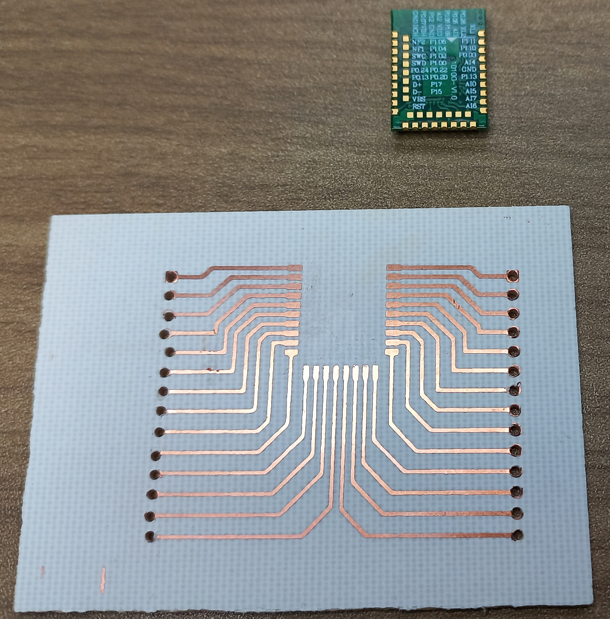
The (unofficial) Dublin Maker Badge for 2022 will hopefully be based on an NRF52833 module. I got hold of couple and asked a colleague to make a breakout PCB for it to allow me experiment.
The PCB is a little rough but is OK for evaluation purposes. I won’t be using the inner layer of contacts for the module as I can’t solder on to them manually however I should have enough pins in what remains. Luckily the extremely flexible NRF52833 allows for routing of signals to just about any pin. Next step is to the module to the board.
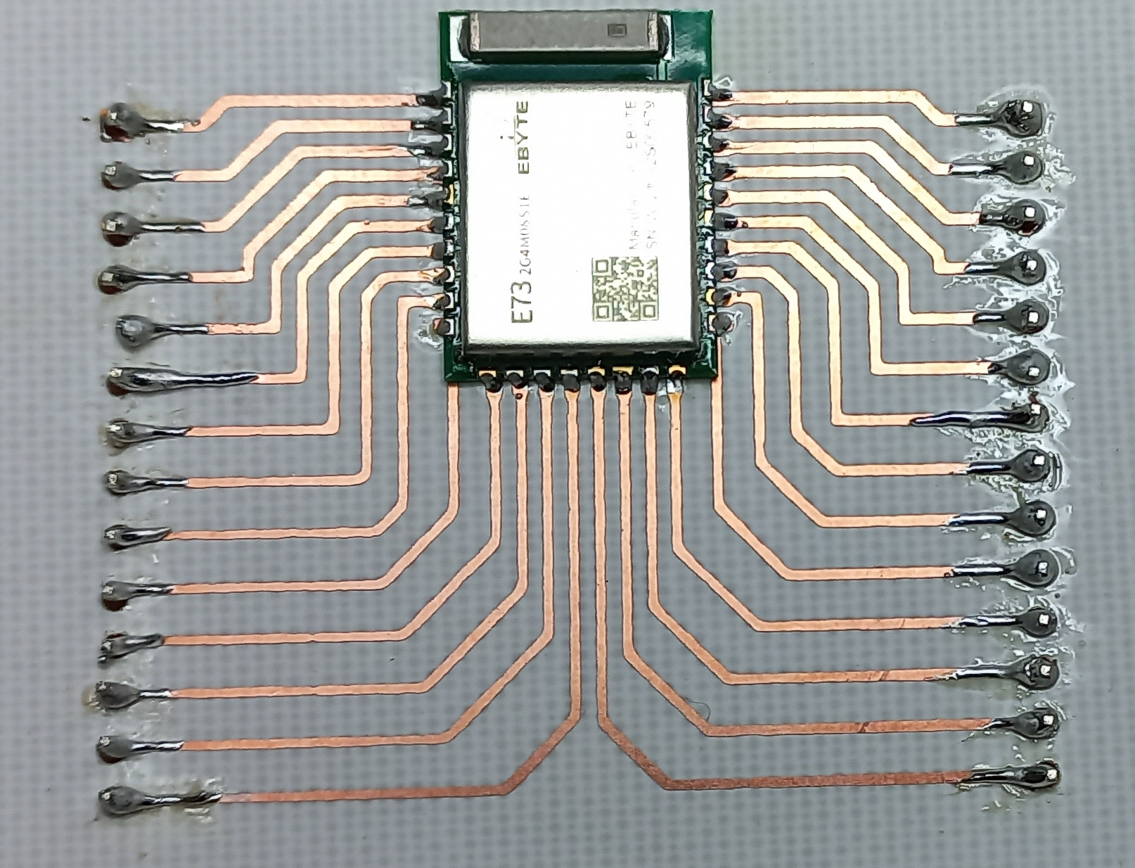
The drill holes for the pin headers have more or less wiped out all of the pads for the pin headers but with some careful soldering I think I got everything wired up. Next step Blinky!
VDD and VDDH are connected to a 3.3V DC supply; the SWD interface is connected to a JLink EDU probe. A simple Zephyr based LED Blinky program was downloaded and tested. The JLink software complained a little about the SWD interface being unstable and it automatically dropped its speed to a lower value. Blinky seemed to work fine; how about a simple BLE example I previously used on the BBC Microbit V2? Well that worked fine too without any changes 🙂
Next step: Interface with a display to see if the SPI interface can be operated at full speed.
It looks like Dublin Maker will actually happen this year :). I had planned a second badge for 2020 but that never happened. I initially thought that I might simply move that plan to this year however testing of the radio link proved to be inadequate for my needs (it used an NRF24L01 module). In the meantime I have been working with Zephyr OS and the BBC Microbit V2. The Microbit is based on an NRF52833 MCU which is capable of doing BLE Mesh networking. This looks quite attractive so I have begun moving my design to this platform. Basic Mesh networking seems to be ok and the graphics routines are working. I need to do a full hardware prototype next using some NRF52833 modules before a batch of badges is produced.
This is the first in a set of posts that will follow the development of the badge.
I got an NRF52840 dongle at Christmas and have been trying to work with Zephyr on it. An initial set of examples is over here. These examples include a simple “Hello World” with a blinking LED, a minimal BLE example and an example that drives an ST7735 display.
Nrf52840 dongle with an ST7735 display
A couple of points about the wiring:
The ST7735 has a built-in 3.3V regulator so it is supplied from the 5V VBus pin.
The serial interface is connected to a USB-Serial converter (not shown). The TX pin (from the NRF) is on P0.20. The RX pin (in to the NRF) is on pin P0.24
In this example a BBC Microbit V2 will be programmed to behave as a step counter and it will report these over its BLE interface. This will not be a primer on Bluetooth. There are plenty of those to be found on the Internet. This post will be specifically about how you work with Zephyr and BLE on the Microbit V2.
BLE Roles for the BBC Microbit and a mobile phone
When your phone connects to a bluetooth device such as a pedometer it takes on a role defined by the Bluetooth SIG as “Central”. The pedometer or other device’s role is “Peripheral”. The central device initiates a connection with the peripheral. The peripheral device can advertise services which contain characteristics that can be read or written. They can also send notifications to the central device should a sensor value change. These services are identified using numeric values. In this example a 128 bit UUID of 00000001-0002-0003-0004-000000000000 is used to identify a step-count service which has a single characteristic (the actual step-count value) with a UUID of 00000001-0002-0003-0004-000000000005
This step count service is defined in Zephyr as follows:
The characteristic contained within this service is defined as follows:
// ********************[ Start of First characteristic ]**************************************
#define BT_UUID_STEPCOUNT_ID  BT_UUID_128_ENCODE(1, 2, 3, 4, (uint64_t)5)
static struct bt_uuid_128 stepcount_id=BT_UUID_INIT_128(BT_UUID_STEPCOUNT_ID); // the 128 bit UUID for this gatt value
uint32_t stepcount_value=0; // the gatt characateristic value that is being shared over BLE
static ssize_t read_stepcount(struct bt_conn *conn, const struct bt_gatt_attr *attr, void *buf, uint16_t len, uint16_t offset);
static ssize_t write_stepcount(struct bt_conn *conn, const struct bt_gatt_attr *attr, const void *buf, uint16_t len, uint16_t offset, uint8_t flags);
// Callback that is activated when the characteristic is read by central
static ssize_t read_stepcount(struct bt_conn *conn, const struct bt_gatt_attr *attr, void *buf, uint16_t len, uint16_t offset)
{
	printk("Got a read %d\n",stepcount_value);
	const char *value = (const char *)&stepcount_value; // point at the value in memory
	return bt_gatt_attr_read(conn, attr, buf, len, offset, value, sizeof(stepcount_value)); // pass the value back up through the BLE stack
}
// Callback that is activated when the characteristic is written by central
static ssize_t write_stepcount(struct bt_conn *conn, const struct bt_gatt_attr *attr,
			 const void *buf, uint16_t len, uint16_t offset,
			 uint8_t flags)
{
	uint8_t *value = attr->user_data;
	printk("Got a write %d\n",len);
	if (len == sizeof(stepcount_value)) // check that the incoming data is the correct size
	{
		memcpy(value, buf, len); // copy the incoming value in the memory occupied by our characateristic variable
	}
	else
	{
		printk("Write size is incorrect.  Received %d bytes, need %d\n",len,sizeof(stepcount_value));
	}
	return len;
}
// Arguments to BT_GATT_CHARACTERISTIC = _uuid, _props, _perm, _read, _write, _value
#define BT_GATT_CHAR1 BT_GATT_CHARACTERISTIC(&stepcount_id.uuid,BT_GATT_CHRC_READ | BT_GATT_CHRC_WRITE |  BT_GATT_CHRC_NOTIFY, 	BT_GATT_PERM_READ | BT_GATT_PERM_WRITE, read_stepcount, write_stepcount, &stepcount_value)
// ********************[ End of First characteristic ]****************************************
As you can see from both of these definitions there are lots of C-macros involved. These are included to help the developer avoid some of the lower level details. The characteristic stores its value in the integer stepcount_value. The characteristic is defined as having the following properties: Read, Write and Notify.
If the central device issues a read requent then the function read_stepcount is called. This function copies the the contents of stepcount_value to a buffer (buf) which is then passed back to the central device.
If the central device writes to the microbit the function write_stepcount will be called. This copies data from a buffer passed by the lower level of the BLE stack into the memory occupied by stepcount_value.
void main(void)
{
	int err;
	int old_stepcount = 0;
	err = lsm303_ll_begin();
	if (err < 0)
	{
		 printk("\nError initializing lsm303.  Error code = %d\n",err);
         while(1);

	}
	err = bt_enable(NULL);
	if (err) {
		printk("Bluetooth init failed (err %d)\n", err);
		return;
	}
	bt_ready(); // This function starts advertising
	bt_conn_cb_register(&conn_callbacks);
	printk("Zephyr Microbit V2 minimal BLE example! %s\n", CONFIG_BOARD);
	if (lsm303_countSteps(&stepcount_value) < 0)
	{
		printk("Error starting step counter\n");
		while(1);
	}

	while (1) {
		k_msleep(100);
		// int bt_gatt_notify(struct bt_conn *conn, const struct bt_gatt_attr *attr, const void *data, u16_t len)
		// conn: Connection object. (NULL for all)
		// attr: Characteristic Value Descriptor attribute.
		// data: Pointer to Attribute data.
		// len: Attribute value length.
		if (active_conn)
		{
			if (stepcount_value != old_stepcount) // only send a notification if the data changes
			{
				old_stepcount = stepcount_value;
				bt_gatt_notify(active_conn,&my_service_svc.attrs[2], &stepcount_value,sizeof(stepcount_value));
			}
		}
	}
}
It begins by initializing the LSM303 accelerometer on the Microbit. It then starts bluetooth advertising. The main loop sleeps for 100ms and then sends an update to the central device if there is an active BLE connection and if there has been a change to the step-count value.
Some significant changes need to be made to prj.conf to enable Bluetooth. On such change is this:
CONFIG_BT_DEVICE_NAME=”Microbit V2 BLE”
This allows you set the name that the microbit will broadcast when advertising its presence.
The BBC Microbit V2 includes an LSM303AGR IC. This can sense acceleration and magnetic fields in three dimensions. It’s typical use is for tracking orientation and direction of motion. It communicates with the NRF52833 using an I2C (Inter-Integrated Circuit) serial bus. This has two signal lines as shown in the extract from the schematic below:
I2C_INT_SCL : Serial clock line for internal I2C communications
I2C_INT_SDA : Serial data line for internal I2C communications.
The phrase “internal” is used as these signals are not brought out to the edge connector and are used for on-board communications only.
A third connection called I2C_INT_INT allows the LSM303 interrupt the NRF52833 when something “interesting” happens e.g. the device is dropped or tapped.
The trace below shows the a data exchange between the NRF52833 and the LSM303. The I2C_INT_SCL line is used to pace the transmission and reception of data. This signal is generated by the NRF52833 which is playing the role of a master or controller device; the LSM303 is a slave or peripheral device. The trace shows two signals and also a higher level interpretation of what is going between the devices.
The I2C transaction begins with a Start signal. This is a High-Low transition of the SDA line when the SCL is high. Next follows an address value. Each I2C device has a manufacturer set 7 or 10 bit address, this discussion will deal with 7 bit addresses only. Several different devices can exist on the same I2C bus. When a controller wishes to communicate with a peripheral it must first send the peripheral’s address. Other I2C devices on the bus effectively disconnect from the bus for the remainder of that transaction. An additional bit is added just after the 7 bit address called the Read/Write bit. If this bit is a 0 then a write transaction is about to take place; if it’s a 1 then a read operation will follow. Altogether then the controller sends 8 bits at the start of a transaction : the 7 bit address and an R/W bit. It then sets it’s SDA signal to a high impedance state so that it can listen for a returning signal from the peripheral.
If a peripheral on the I2C bus recognizes the 7 bit address it pulls the SDA line to 0. This is an Acknowledge signal. If there is no peripheral with that address then the SDA line will remain high.
The LSM303 has a number of internal registers. Typical interactions with it involve reading from and writing to these registers. Immediately following the I2C addressing phase the register number of interest is transmitted. In the above trace this value is hex AA. The slave acknowledges this write. The transaction shown above actually consists of two parts. The first part writes the register number of interest to the LSM303, the second part reads data from that register (and the one following). The controller indicates this by sending a start signal again (labelled Sr = repeated start). If that had been the end of the transaction the controller would have sent a stop signal.
The last phase of this transaction is a read of the registers within the LSM303. Once again the I2C address is sent but this time the least significant bit i.e. the R/W bit is a 1 to indicate that a register read is required. Following the Ack from the peripheral the controller puts its SDA line into a high impedance or listening state and outputs 16 clock pulses. The peripheral takes control of the SDA line and sends back two bytes of data. A Negative Acknowledge or NACK signal is sent by the controller to indicate that the transaction is done. It follows this by sending a Stop signal (a low to high transition of the SDA line when the SCL line is high).
Overall the transaction in the graph above is a read of registers 0x2A and 0x2B in the LSM303. These contain the low and high byte values for the Y acceleration. Each byte could have been read separately (slower) but the LSM303 allows you read multiple bytes in successive registers by setting the most significant bit of the register number to a ‘1’ so register number 0xAA represents a transaction involving register number 0x2A and subsequent registers within the LSM303.
The code for interfacing with the LSM303 is shown below. Inside the function lsm303_ll_begin a pointer to the I2C device structure for device I2C_1 is obtained. The code then attempts to read a particular register within the LSM303 which contains a known value. This is a mechanism to allow us check to see whether the device is actually on the bus. In this case, the register number in question is 0x0f and it should contain the value 0x33 (decimal 51). If all of this works ok the function then sets the operating mode of the accelerometer : +/- 2g range with 12 bit resolution.
The function lsm303_ll_readAccelY performs the transaction shown in the I2C trace above. It makes use of the Zephyr I2C API function i2c_burst_read. This function takes the following arguments:
A pointer to the I2C device
The address of the I2C peripheral
The number of the register from which you want to read
A pointer to a receive buffer
A count of the number of bytes required.
Two other function lsm303_ll_readRegister and lsm303_ll_writeRegister facilitate reading and writing of single bytes from/to registers.
Note the way lsm303_ll_readAccelY combines the low and high bytes and scales them to a value of acceleration scaled up by a factor of 100.
static const struct device *i2c;
int lsm303_ll_begin()
{
	int nack;
	uint8_t device_id;
	// Set up the I2C interface
	i2c = device_get_binding("I2C_1");
	if (i2c==NULL)
	{
		printf("Error acquiring i2c1 interface\n");
		return -1;
	}
	// Check to make sure the device is present by reading the WHO_AM_I register
	nack = lsm303_ll_readRegister(0x0f,&device_id);
	if (nack != 0)
	{
		printf("Error finding LSM303 on the I2C bus\n");
		return -2;
	}
	else
	{
		printf("Found LSM303.  WHO_AM_I = %d\n",device_id);
	}
	lsm303_ll_writeRegister(0x20,0x77); //wake up LSM303 (max speed, all accel channels)
	lsm303_ll_writeRegister(0x23,0x08); //enable  high resolution mode +/- 2g

	return 0;
}

int lsm303_ll_readAccelY() // returns Temperature * 100
{
	int16_t accel;
	uint8_t buf[2];
	buf[0] = 0x80+0x2a;
	i2c_burst_read(i2c,LSM303_ACCEL_ADDRESS,0xaa, buf,2);
	accel = buf[1];
	accel = accel << 8;
	accel = accel + buf[0];
	accel = accel / 16; // must shift right 4 bits as this is a left justified 12 bit result
	// now scale to m^3/s * 100.
	// +2047 = +2g
	int accel_32bit = accel; // go to be wary of numeric overflow
	accel_32bit = accel_32bit * 2*981 / 2047;
    return accel_32bit;
}

int lsm303_ll_readRegister(uint8_t RegNum, uint8_t *Value)
{
	    //reads a series of bytes, starting from a specific register
    int nack;
	nack=i2c_reg_read_byte(i2c,LSM303_ACCEL_ADDRESS,RegNum,Value);
	return nack;
}
int lsm303_ll_writeRegister(uint8_t RegNum, uint8_t Value)
{
	//sends a byte to a specific register
    uint8_t Buffer[2];
    Buffer[0]= Value;
    int nack;
	nack=i2c_reg_write_byte(i2c,LSM303_ACCEL_ADDRESS,RegNum,Value);
    return nack;
}
These functions can be used as follows to send the Y acceleration to the serial port
void main(void)
{
	int ret;

	ret = lsm303_ll_begin();
	if (ret < 0)
	{
		printf("\nError initializing lsm303.  Error code = %d\n",ret);
		while(1);
	}
	while(1)
	{
        printf("Accel Y (x100) = %d\n",lsm303_ll_readAccelY());
         k_msleep(100);

	}
}
This particular example illustrates a low level (hence the “ll” in the function names) transaction with the LSM303 over the I2C bus. Zephyr includes a driver for the LSM303 (and may other I2C devices) which performs initialization and scaling.
The following modifications have to be made to prj.conf to trigger the inclusion of the I2C driver into the program:
The NRF52833 has a 12 bit, 8 channel Analogue to Digital Converter (ADC) which allows it to convert signals from analogue sensors into numbers that can be used in calculations. The NRF52833 does not have a Digital to Analogue Converter (DAC) (this is quite common for microcontrollers). Instead it fakes an analogue output capability by doing Pulse Width Modulation (PWM) i.e. by sending a square wave to an output pin and varying the percentage time the pin is high. This allows it to control the average output voltage on that pin. A simple RC filter can be used to filter out the pulses and leave a variable output voltage.
Reading an analogue input
In this example an analogue input is sent to RING0 (there are 5 holes on the Microbit that are designed to accept banana plugs. Ring 0 is the left-most hole when the board is viewed from the speaker side). The RING0 input is connected to Port 0 bit 2 (P0.2) which is also referred to as AIN0 (analogue input 0) in the NRF52833 data sheet. This pin must be configured for operation as an analogue input. This is done using an adc_channel_cfg as shown below.
/*
 * The internal voltage reference is 0.6V
 * The permissable gains are 1/6, 1/5, 1/4, 1/3, 1/2, 1, 2 and 4
 * If a gain of 1/5 is selected then the ADC range becomes 0 to 3V
 */
static const struct device *adc;
// Will read from analog input on P0.2 which is RING 0 on the microbit v2
#define ADC_PORT_BIT 2
struct adc_channel_cfg channel_cfg = {
		/* gain of 1/5 */
		.gain = ADC_GAIN_1_5,
		/* 0.6V reference */
		.reference = ADC_REF_INTERNAL,
		/* sample and hold time of 3us is the default (0 setting) on the NRF52833 */
		.acquisition_time = ADC_ACQ_TIME_DEFAULT,
		/* Channel 0 */
		.channel_id = 0,
		/* AIN0 is specified by setting input_positive to 0+1 i.e. an offset of 1  */
		/* This is as a result of the way the PSELP and PSELN registers work in the NRF52 series of devices */
		/* see page 375 of the NRF52 product specificatoin version : 4452_021 v1.3 */
		.input_positive = 1,
		/* Using single ended conversions */
        .differential = 0
};

int adc_begin()
{
	int ret;
	// Configure the GPIO's
	adc=device_get_binding("ADC_0");
	if (adc == NULL)
	{
		printf("Error acquiring ADC \n");
		return -1;
	}
	ret = adc_channel_setup(adc, &channel_cfg);
	if (ret < 0)
	{
		printf("Error configuring ADC channel 0\n");
		return -2;
	}
	return 0;
}
The NRF52833 can use an internal voltage reference of 0.6V as a basis for ADC conversions as well as fractions of the supply voltage. We will use 0.6V as this is independent of the power supply voltage. Each ADC channel can be scaled by an amplifier. This scaling factor is called “gain” and allows us to control the measurable input voltage range. For example, with a gain of 1 and a voltage reference of 0.6 the ADC will produce its maximum digital output value ((2^12) -1 = 4095) when the input is just 0.6V. If we apply a gain of 1/5 then the measurable input voltage range extends to 3V.
The ADC is of the successive-approximation variety and as such, it requires a stable input voltage during the conversion process. A sample-and-hold circuit (a little capacitor) is used to take a snapshot of the input voltage which is then converted. Capacitors take time to charge and it can happen that insufficient time is allowed for this in which case the snapshot will be different to the actual input voltage at that instant. We can avoid this by allowing a long charging period however this reduces the maximum sampling rate. The acquisition_time field of the adc_channel_config structure allows you control this charging period. It is set to the default of 3 microseconds above.
The channel_id field of the adc_channel_config is used to “name” a particular ADC channel. It is a logical name as opposed to a physical channel in the case of the NRF52833. We associate this adc channel with a particular analogue input using the input_positive field. If we want to use AIN0 this field should be set to ‘1’, for AIN1 this should be 2 etc. i.e. one more than the analogue input channel number as described in the NRF52833 datasheet. The reason for the addition of ‘1’ is to do with the way registers are programmed in this particular microcontroller.
The adc_begin function gets a device structure pointer for the ADC and configures a single channel for use.
To make a reading from the ADC we have to pass an adc_sequence structure to the adc_read
static int16_t channel_0_data;  // This will hold the adc result

struct adc_sequence sequence = {
		/* This is a bitmask that tells the driver which channels to convert : bit n = 1 for channel n */
		.channels    = (1 << 0),
		/* Where will the data be stored (could be an array if there are multiple channels to convert */
		.buffer      = &channel_0_data,
		/* buffer size in bytes, not number of samples */
		.buffer_size = sizeof(channel_0_data),
		/* 12 bit resolution */
		.resolution  = 12,
		/* nulls for the rest of the fields */
		.options = NULL,
		.calibrate = 0,
		.oversampling = 0,
};
int adcread()
{
	int ret;
	ret = adc_read(adc, &sequence);
	return channel_0_data;
}
In our case we are doing a sequence of 1 conversion so a single 16 bit result is stored to the channel_0_data variable. The address and size of an array can be passed here instead if multiple samples are to be taken.
Analogue output
As mentioned above, the NRF52833 does not have a DAC so it uses PWM instead to simulate a continuously variable analogue output. This requires us to add a couple of elements to our project. We need C functions to initialize the PWM output and also to send values to it as shown below
static const struct device *pwm;
int pwm_begin()
{
	int ret;
	// Configure the GPIO's
	pwm=device_get_binding("PWM_0");
	if (pwm == NULL)
	{
		printf("Error acquiring PWM interface \n");
		return -1;
	}
	return 0;
}
int pwm_write(uint16_t value)
{

	return pwm_pin_set_usec(pwm,3,PWM_PERIOD_US,value,0);
}
The pwm_begin function acquires a pointer to the device structure for the PWM_0 device. The pwm_write function takes a single argument which is the number of microseconds the associated output pin should be high in each PWM cycle. The constant PWM_PERIOD_US in this example is set to 100 so the incoming parameter to this function should be in the range 0 to 100. The pwm_pin_set_usec function takes 5 arguments:
A pointer to the PWM device structure
The pin number that is to be controlled
The PWM period expressed in microseconds
The PWM high-time expressed in microseconds
A “flags” value which can be used to set the PWM output polarity (0 works fine here)
I have chosen to use P0.3 as the PWM output pin. This is connected to RING1 on the BBC microbit which makes it easy to use with banana plugs. The PWM output can be routed to other pins but I have found that not all of them work (probably due to being configured for use with other peripherals by the OS).
The app.overlay file.
The analogue input and output routines shown above require an additional file be created in the project directory: app.overlay. This file can override and add to settings in the default device tree (dts) file for this device which is to be found in zephyr/boards/arm/bbc_microbit_v2/bbc_microbit_v2.dts. In this file, the adc and pwm devices are disabled. Also, there are no pins assigned to the PWM subsystem. We can fix all of this with the following app.overlay file:
&adc {
	status = "okay";
};
&pwm0 {
	status = "okay";
	ch0-pin = <3>; // P0.3 is labelled RING1 on the microbit. (connected to pin 1 in breakout board)
};
Putting it all together
The following main function reads a value from the ADC and writes a proportional value to the PWM system. The average output voltage should therefore track the input voltage (it will be a little higher because the output switches between 0 and 3.3V. If the input voltage is 3V then the duty will be 100% resulting in an output voltage of 3.3V)
void main(void)
{
	int ret;
	ret = adc_begin();
	if (ret < 0)
	{
		printf("\nError initializing adc.  Error code = %d\n",ret);
		while(1);
	}
	ret = pwm_begin();
	if (ret < 0)
	{
		printf("\nError initializing PWM.  Error code = %d\n",ret);
		while(1);
	}
	while(1)
	{
		uint32_t adcvalue = adc_readDigital();
		printf("ADC Digital = %u\n",adcvalue);
		/* The default version of printf does not support floating point numbers so scale up to an integer */
		printf("ADC Voltage (mV) = %d\n",(int)(1000*adc_readVoltage()));
		pwm_write((adcvalue * PWM_PERIOD_US)/4095);
		k_msleep(100);
	}
}
Note: all examples used in this tutorial can be found in full over here on github
When should you use an operating system?
There is no simple answer here other than this : “When the value it provides is greater than the cost of learning and using it”.
Among the value offerings of operating systems is hardware abstraction, complex library support, communications protocols and security. Developing these features/libraries from scratch is error prone and time consuming. There is no doubt that you will bring a product to market faster by using a good existing OS and it is likely that your maintenance burden will be reduced. You may also find it easier to recruit developers for such an OS in contrast to using a home-grown solution. That said, using an OS, even a free one, is not cost free. You will have to set up a development environment, learn about it’s libraries and API’s and possibly live with a bigger memory footprint, I/O timing jitter, and a higher CPU load. This may then cause you to raise the hardware specification of your MCU. Elicia White, author of Embedded Systems advises that you should consider using an OS for your MCU project once you get into the realms of networking and/or USB. This application domain is IoT so we will take that advice and base our application on an existing embedded operating system.
Choosing an OS
Factors affecting your choice: Cost, Code size (Flash memory), RAM usage, Hardware support, ongoing support and updates, licensing, value added features such as integration with IoT services such as remote firmware update and messaging. In the case of the BBC Microbit V2 there are not that many options for an embedded OS. The MCU at the heart of the Microbit-V2 is an NRF52833 from Nordic semiconductors. Nordic provides a “binary blob” to manage the radio interface and other hardware elements (this is referred to as a soft-device). In many ways this resembles an operating system. Application developers link this blob with their code and interact with it using an API. Embedded operating systems on this platform also interact with the soft-device and provide an additional range of services. Embedded OS options for the NRF52833 include:
FreeRTOS, Zephyr, and Riot OS (there may be more). Of these Zephyr stood out as having a very active development community. It is licensed using the Apache 2.0 license which is quite permissive. Nordic Semiconductors also seem to be actively supporting this OS so for these reasons, Zephyr was chosen.
What is Zephyr?
Zephyr is a designed to run on microcontrollers with a limited amount of ROM, RAM and CPU resources. It targets a range of MCU cores including various ARM devices, Intel x86, RISC-V and ESP32. This means that application development skills you acquire on one hardware platform can be transferred to other devices.
When we use the phrase “Operating System” we may be inclined to think of desktop operating systems such as Windows, OS-X, Linux etc. Desktop OS’s allow you load and run programs dynamically. Embedded operating systems such as Zephyr do not work like this. The OS and application are compiled together into one single file which is programmed on the target device. When the system starts up, the OS is booted and your application runs. Typically, your application is the only one running on the target system (it may have multiple threads but that’s another story). In this sense, you can consider OS’s such as Zephyr to be like a library that you might link with your own code.
Setting up a working environment.
In order to build applications for Zephyr you need to set up a compiler, libraries, header files and a host of other tools. This environment is sometimes referred to as a toolchain. Detailed instructions for setting up Zephyr on your computer are available here: https://docs.zephyrproject.org/latest/getting_started/index.html
Note: At the end of the installation instructions you are told to test your toolchain and board by compiling a simple blinking LED example. This will not work with the Microbit-V2 as there is no “simple” user LED on the board. You can however build the hello world example as follows:
west build -p auto -b bbc_microbit_v2 samples/hello_world –pristine
The output from this program is sent to your PC using a built-in USB-Serial converter in the Microbit. On Linux this will appear as device /dev/ttyACM0 typically. On Windows this will appear as COM3 or similar. Run a dumb terminal application with a baud-rate of 115200bps, 8 data bits and no parity and you should hopefully see the output on you PC screen.
The BBC Microbit (V2) hardware
The Microbit V2 has a number of built-in peripherals that are accessible by the programmer. These are shown above. The LED matrix is a arranged in a 5 row by 5 column matrix with one GPIO (GPIO= General Purpose Input Output port) row pin supplying (sourcing) current and a GPIO column pin absorbing (sinking) current. There are also two push buttons which are pulled high via 10k resistors; when a button is pressed it pulls a GPIO pin low. The edge connector provides access to GPIO pins some of which are also used by the onboard peripherals. So, if you plan to use an edge connector pin be sure that it does not interfere with an onboard peripheral that you also intend to use.
The onboard LSM303AGR is a 3 axis accelerometer and 3 axis magnetometer. It is used for motion sensing. It is connected to the NRF52833 via an I2C bus (signals can be viewed on board test points)
Zephyr and I/O pins.
Zephyr uses the a system called devicetree to identify GPIO pins, I2C devices and other peripherals. It is quite confusing for beginners (like me) to use and makes extensive use of C macros. In an effort to avoid turning this into a tutorial on devicetree the example projects will make minimal use of devicetree and will instead use Zephyr API’s to access I/O where possible.
Making patterns on the LED matrix
The full code for this example is in the project led_matrix
The LED matrix is wired as shown above. The Input/Output list is as follows:
Signal
Port
Bit
Source/Sink
ROW1
GPIO0
21
Source
ROW2
GPIO0
22
Source
ROW3
GPIO0
15
Source
ROW4
GPIO0
24
Source
ROW5
GPIO0
19
Source
COL1
GPIO0
28
Sink
COL2
GPIO0
11
Sink
COL3
GPIO0
31
Sink
COL4
GPIO1
5
Sink
COL5
GPIO0
30
Sink
All of these pins must be configured as outputs (because your program will set them high or low). The Source pins must be a High to light an LED and the Sink pins must be Low.
The matrix can be configured in code as follows:
#define ROW1_PORT_BIT 21
#define ROW2_PORT_BIT 22
#define ROW3_PORT_BIT 15
#define ROW4_PORT_BIT 24
#define ROW5_PORT_BIT 19

#define COL1_PORT_BIT 28
#define COL2_PORT_BIT 11
#define COL3_PORT_BIT 31
#define COL4_PORT_BIT 5
#define COL5_PORT_BIT 30

static const struct device *gpio0, *gpio1;
int matrix_begin()
{
    int ret;
    // Configure the GPIO's
    gpio0=device_get_binding("GPIO_0");
    if (gpio0 == NULL)
    {
        printf("Error acquiring GPIO 0 interface\n");
        return -1;
    }
    gpio1=device_get_binding("GPIO_1");
    if (gpio0 == NULL)
    {
        printf("Error acquiring GPIO 1 interface\n");
        return -2;
    }
    ret = gpio_pin_configure(gpio0,ROW1_PORT_BIT,GPIO_OUTPUT);
    ret = gpio_pin_configure(gpio0,ROW2_PORT_BIT,GPIO_OUTPUT);
    ret = gpio_pin_configure(gpio0,ROW3_PORT_BIT,GPIO_OUTPUT);
    ret = gpio_pin_configure(gpio0,ROW4_PORT_BIT,GPIO_OUTPUT);
    ret = gpio_pin_configure(gpio0,ROW5_PORT_BIT,GPIO_OUTPUT);

    ret = gpio_pin_configure(gpio0,COL1_PORT_BIT,GPIO_OUTPUT);
    ret = gpio_pin_configure(gpio0,COL2_PORT_BIT,GPIO_OUTPUT);
    ret = gpio_pin_configure(gpio0,COL3_PORT_BIT,GPIO_OUTPUT);
    ret = gpio_pin_configure(gpio1,COL4_PORT_BIT,GPIO_OUTPUT);
    ret = gpio_pin_configure(gpio0,COL5_PORT_BIT,GPIO_OUTPUT);

    matrix_all_off();
    return 0;
}
The Zephyr API calls used are:
get_device_binding and gpio_pin_configure
The first of these get_device_binding returns a pointer to a Zephyr device structure. The behavior is similar to the file open function fopen in C. If the device can’t be found a null is returned otherwise you use the returned value for future operations on that device. The argument passed to get_device_binding is GPIO_0 (and later GPIO_1). This string is used to search the device tree and if a matching device label is found the function returns a pointer to it’s device structure. So the first few lines of matrix_begin retrieve pointers to the gpio0 and gpio1 devices.
The gpio_pin_configure function takes three arguments:
A pointer to the device structure for that GPIO port
Once again, three arguments are required: you must tell it the port, the bit number and whether the pin is to be High (1) or Low (0).
The function below can be used to put a pattern on the matrix. The row and column states are passed as the 5 least significant bits of the rows and cols parameters.
Finally, here is the main function that generates the matrix pattern. Note the inversion of the cols variable in the call to matrix_put_pattern. This is because column bits are active low (they sink current).
Other bits on the edge connector can be used in a similar way. For example looking at the extract from the Microbit V2 schematic below we can see that P2 or Ring 0 is connected to GPIO port 0, bit 2.
Reading inputs.
The Microbit has two push buttons that pull low when pushed. The configuration of these inputs follows the same pattern as the outputs above. First identify the port and bit number involved and use gpio_pin_configure to configure them as digital inputs (GPIO_INPUT). To read a pin state we call on gpio_pin_get passing two arguments: a pointer to the port device structure and the bit number in question. The function will return 0 or 1 depending on the pin state or and error code (negative value ) if something went wrong.
// Both buttons are on GPIO0
#define BUTTON_A_PORT_BIT 14
#define BUTTON_B_PORT_BIT 23
static const struct device *gpio0;
int get_buttonA()
{
    return gpio_pin_get(gpio0,BUTTON_A_PORT_BIT);
}
int get_buttonB()
{
    return gpio_pin_get(gpio0,BUTTON_B_PORT_BIT);
}
int buttons_begin()
{
    int ret;
    // Configure the GPIO's
    gpio0=device_get_binding("GPIO_0");
    if (gpio0 == NULL)
    {
        printf("Error acquiring GPIO 0 interface\n");
        return -1;
    }
    ret = gpio_pin_configure(gpio0,BUTTON_A_PORT_BIT,GPIO_INPUT);
    ret = gpio_pin_configure(gpio0,BUTTON_B_PORT_BIT,GPIO_INPUT);
    return 0;
}

void main(void)
{
    int ret;
    uint8_t rows = 1;
    uint8_t cols = 1;
    ret = matrix_begin();
    if (ret < 0)
    {
        printf("\nError initializing LED matrix.  Error code = %d\n",ret);
        while(1);
    }
    ret = buttons_begin();
    if (ret < 0)
    {
        printf("\nError initializing buttons.  Error code = %d\n",ret);
        while(1);
    }
    while(1)
    {
        matrix_put_pattern(rows, ~cols);
        if (get_buttonA()==0)
        {
            cols = cols << 1; // only change pattern when button A pressed
        }
        if (get_buttonB()==0)
        {
            rows = cols = 1; // reset pattern to start condition
        }
        if (cols > 16)
        {
            cols = 1;
            rows = rows << 1;
            if (rows > 16)
            {
                rows = 1;
            }
        }
        k_msleep(100);
    }
}
The full code for this example is in the project buttons_with_matrix
The above example uses “polling” i.e. continuous reading of the state of the inputs to decide what to do. This is inefficient as the CPU is running at full speed and may miss inputs if it is doing some other task. An alternative approach is to use interrupts which will trigger the execution of a particular function (the interrupt handler) when a hardware event occurs. If the CPU is busy doing something else this task will be suspended while the interrupt handler executes (so long as interrupts have been enabled. The example below is a modification of the above button code.
static fptr button_a_user_handler = NULL;
static struct gpio_callback button_a_cb;
static void button_a_handler(const struct device *dev, struct gpio_callback *cb, uint32_t pins)
{
    printk("interrupt\n");
    if (button_a_user_handler)
    {
        button_a_user_handler();
    }
}
int attach_callback_to_button_a(fptr callback_function)
{
    if (gpio_pin_interrupt_configure(gpio0,BUTTON_A_PORT_BIT,GPIO_INT_EDGE_FALLING) < 0)
    {
        printk("Error configuring interrupt for button A\n");
    }
    gpio_init_callback(&button_a_cb, button_a_handler, (1 << BUTTON_A_PORT_BIT) );
    if (gpio_add_callback(gpio0, &button_a_cb) < 0)
    {
        printk("Error adding callback for button A\n");
    }
    else
    {
        // success so far so use the user supplied callback function
        button_a_user_handler = callback_function;
    }
    return 0;
}
The function gpio_pin_interrupt_configure takes three arguments: a reference to the GPIO port, the bit number in question and a flag to indicate whether you want to be interrupted on falling or rising edges etc.
The function gpio_init_callback is used to prepare a structure of type gpio_callback which will be used in a follow-on call to the gpio_add_callback function. gpio_init_callback takes three arguments: the address of the structure that will be prepared, the address of the function that will handle the callback and bitmask identifying which pins will trigger the callback (note the difference between the third parameter here and the second parameter for gpio_pin_interrupt_configure).
The function gpio_add_callback is the last step in setting up interrupts. It takes two arguments : a reference to the GPIO port and the structure that was prepared by gpio_init_callback.
Following all of this, when a falling edge (a button press) happens the function button_a_handler will be called automatically. The declaration of this function is a little complex so I have decided to hide this from the typical user. Instead, the user calls on attach_callback_to_button_a and passes the address of a function they would like called when the button is pressed. This address is stored and when button_a_handler is activated it will call the user function there.
The main function matching this example is shown below.
The full code for this example is in the project buttons_with_matrix_with_interrupts
Note the use call to attach_callback_to_button_a takes a single argument – the address of the function you would like to run. In this case, the callback function moves the led matrix pattern variables along a step each time the button is pressed. Also note the use of the volatile keyword.
I wanted to continue my investigation of the Microbit V2 and Zephyr by adding an external I2C device. The BMP280 module I chose is able to report back temperature and atmospheric pressure. I thought it would be nice to combine this with the earlier ST7789 example to produce a live reading of temperature and pressure on the display. This required a slight modification to the ST7789 setup as it is not possible to use both I2C1 and SPI1 in the same NRF52833 (microbit) project. This was easily fixed as the NRF52833 has SPI interfaces 0 to 2. I chose SPI1 which led me to write the following app.overlay file:
&spi2 {
 compatible = "nordic,nrf-spi";
 status = "okay";
 sck-pin = <17>;
 mosi-pin = <13>;
 /* Redirecting MISO to a pin that is not connected on the microbit v2 board */
 miso-pin = <27>;
 clock-frequency = <1000000>;
};
&i2c1 {
	compatible = "nordic,nrf-twim";
	status = "okay";
	sda-pin = < 0x20 >; // P1.0 = pin reference 32+0 = I2c_EXT_SDA
	scl-pin = < 0x1a >; // P0.26 = pin reference 0x1a = I2C_EXT_SCL
};
I wanted to learn about using an external SPI device with the BBC Microbit V2. I ported my ST7789 library over to a Zephyr based program shown running on the Microbit and it is shown in operation above. The SPI interface runs at a fairly slow 8MHz which I believe (for now) is the maximum for this interface. As a result, screen updates are not super quick but probably good enough for a simple user interface.
The display library supports the following functions: