Dublin Maker 2022 took place on the 23rd of July in Merrion Square in Dublin. Despite some initial rain it turned out to be a great day out (as usual). Lots of photos of the event can be seen here:
Thanks to all the committee for organizing this great event.
The DMB 2022 badge runs Zephyr!
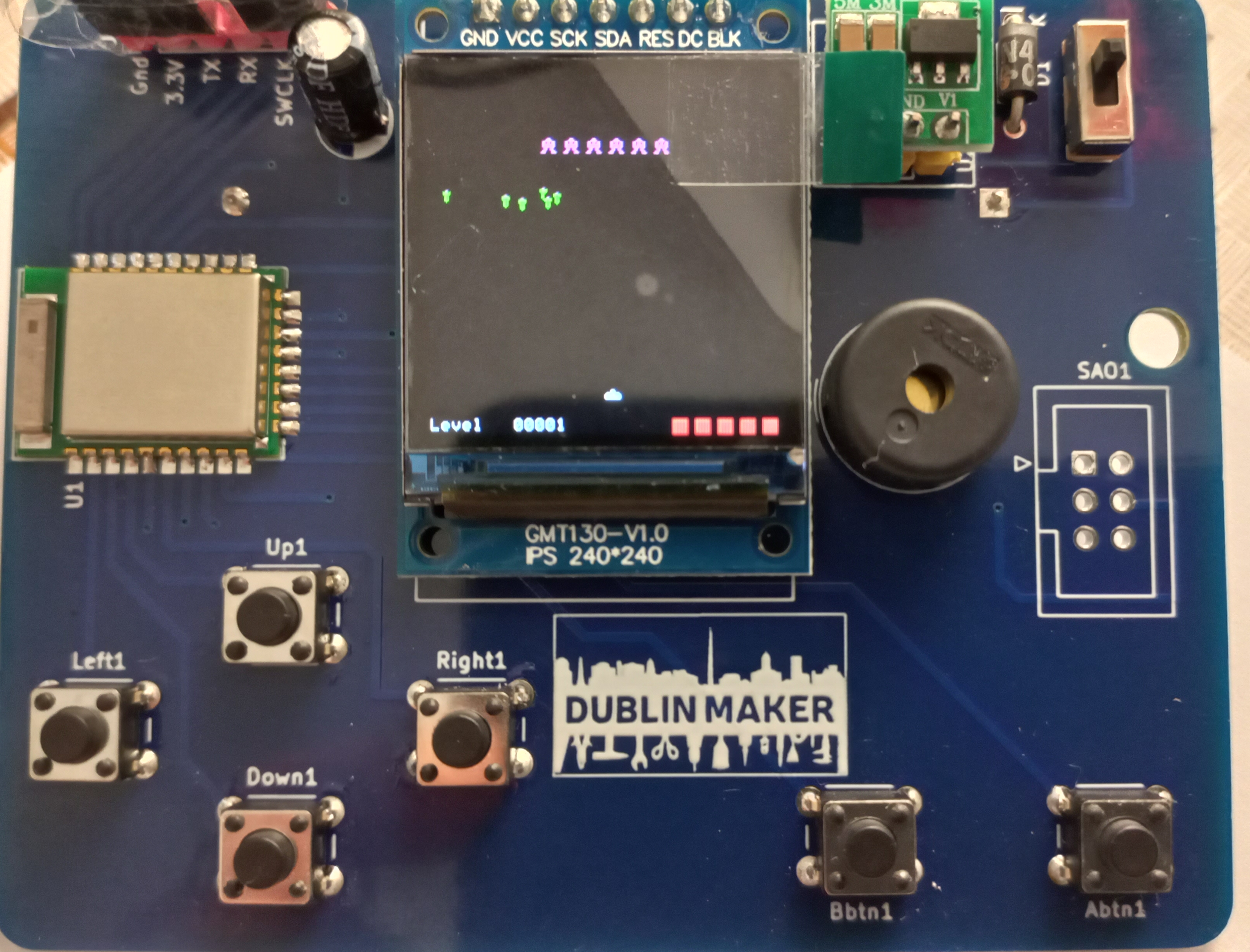
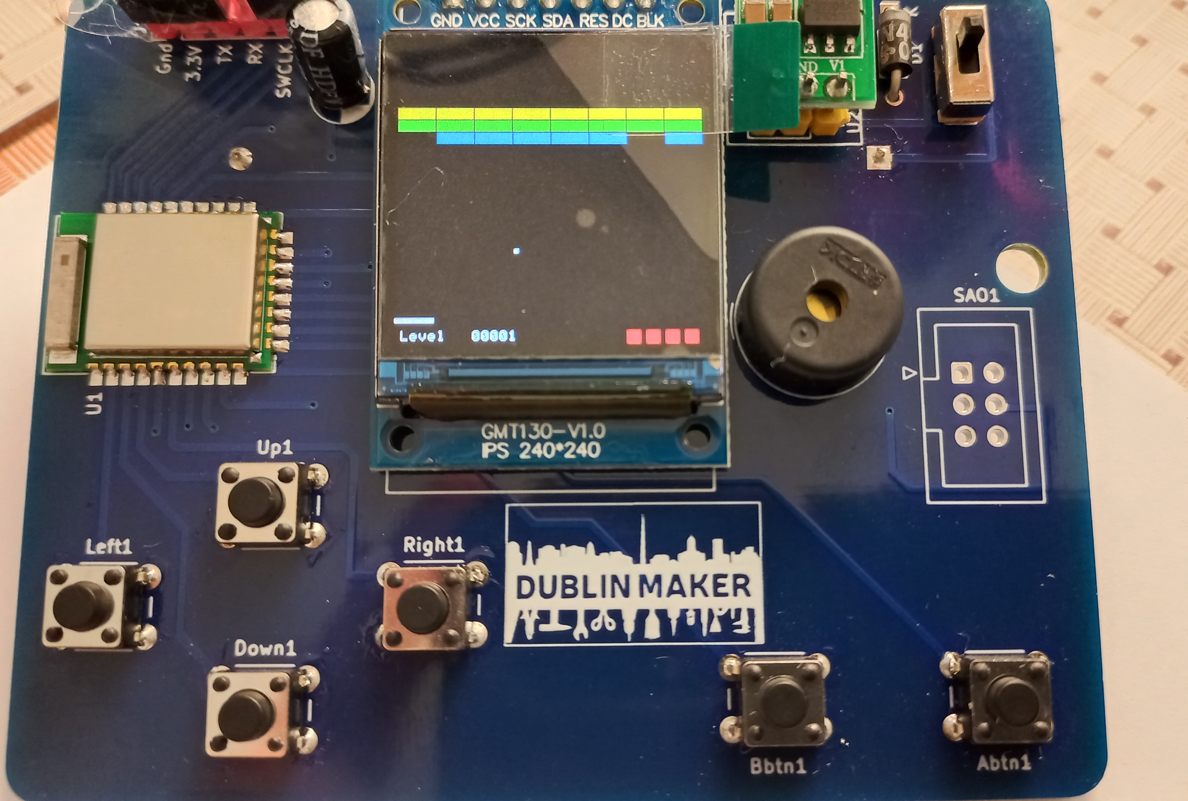
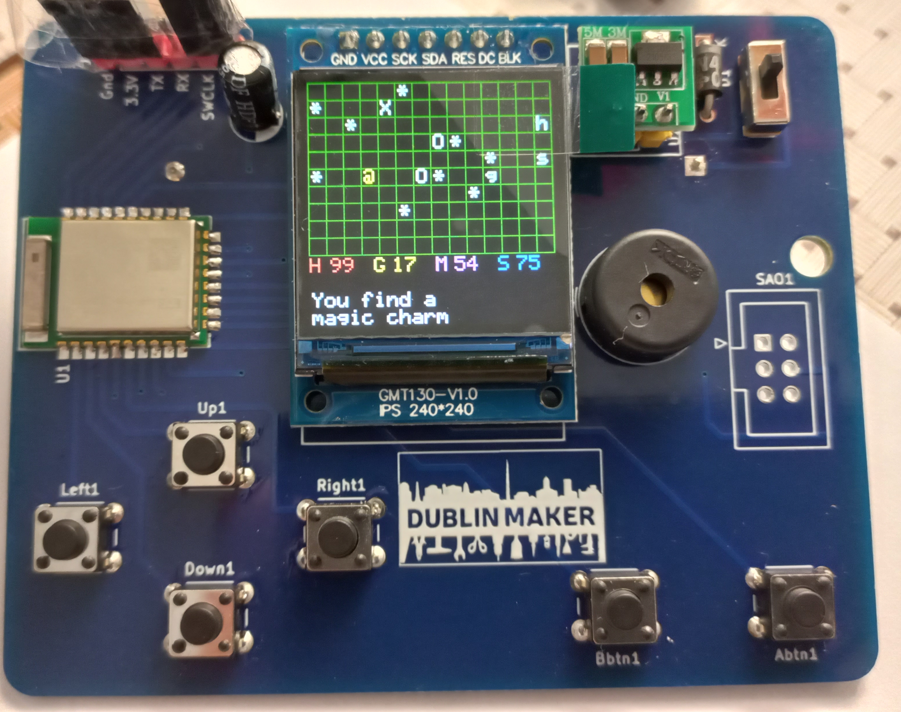
I finally finished (sort of) the code for the badge. It contains a number of games including:
Galaga
Galaga
Brici (like breakout)
Brici
An adventure game called Microrealms
Microrealms
A version of the Battleship game for two players (we did this on paper when were in school)
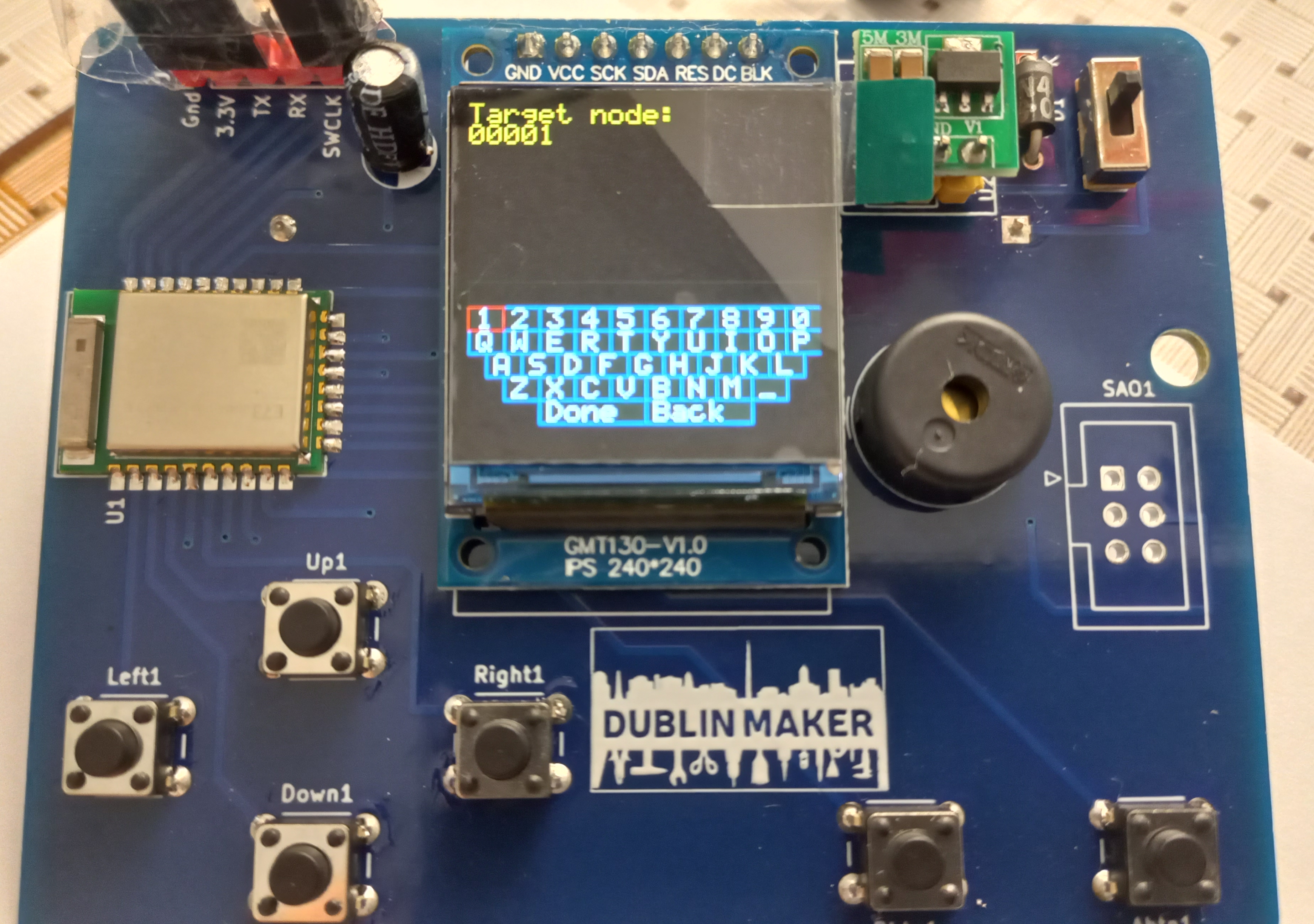
And a communications “applet”
This uses BLE Mesh which is made possible by Zepher OS (version 2.6.0). When the badge is idle it shows the Dublin Maker logo which includes a city skyline containing “The spire”. This pretends to be a radio antenna as shown below 🙂
This will not be the end of the road for this badge. I plan to add additional software and upgrade to a more recent version of Zephyr although I will have to learn more about the PINCTRL mechanism first.
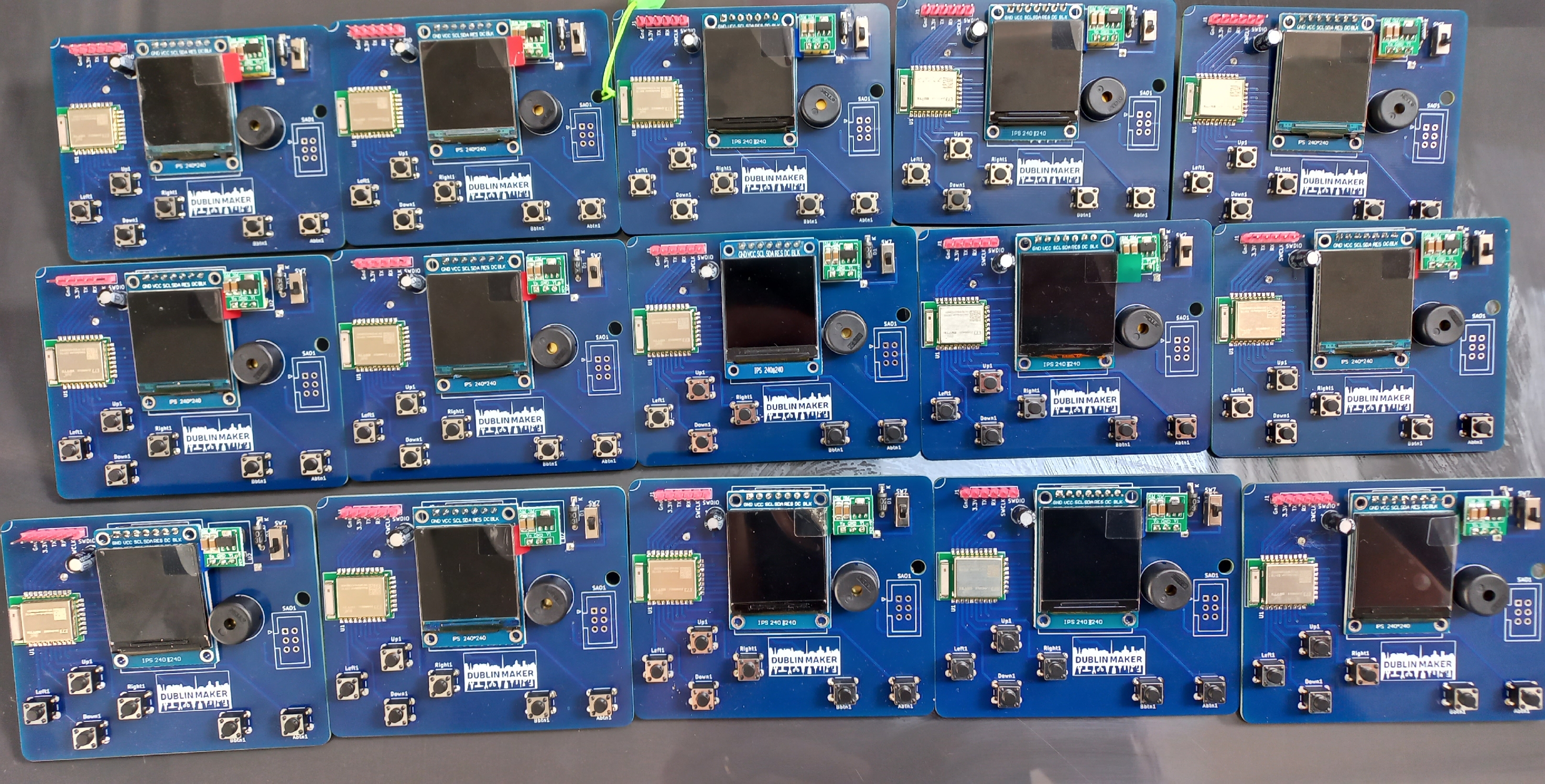
Just completed batch of 15 (unofficial!) badges for Dublin Maker 2022. I plan to make another 10 in the next couple of weeks. Each badge takes about 40 minutes to build and test.
Software is still a work in progress and I hope to have that done soon.
The badge PCB’s arrived! With more than a little trepidation parts were gradually added (checking for the magic smoke at each step) and in the end, everything worked!
Next steps are to make a couple more of them (to test the BLE mesh functionality) and then comes the arguably larger task of developing some games that will exercise the capabilities of the system.
DMB2022 (Dublin Maker Badge for 2022 (not official)) is an electronic badge consisting of an NRF52833 module and a display. The display for the badge is an ST7789 module. It has an SPI interface that is operated at 32MHz. It is configured to use 16 bit RGB colour values arranged as follows:
5 most significant bits : Red
6 middle bits : Green
5 least significant bits : Blue
The NRF52833’s SPI3 is used to drive the display as SPI0 and SPI1 are limited to 8Mbs. SPI3 can operate up to 32Mbs.
The display.cpp module handles all interaction with the ST7789. Lots of LCD displays of this type have a similar pattern of operations.
At startup, the display is first configured which typically involves bringing the device out of low power mode and configuring its colour mode, orientation and optionally its colour palette. The initialization code achieves this by sending commands and data to the display. The D/C signal tells the display whether a command or data byte is being transmitted. If it is Low then a command is being sent; a High level implies data is being sent.
In order to put pixels on the display, the controlling program must first open up an aperture for drawing in. This aperture can range from the entire display to just a single pixel. Once opened, data can be written to the aperture as a continuous stream of bytes. The display performs a raster like operation on the incoming data with display lines auto-wrapping when the data stream reaches the right-hand side of the aperture.
All of the remaining graphic primitives are built on top of this mechanism (with a few performance optimizations). The display class includes the following functions (for now):
I will not do a deep dive on all of the functions, instead I will just focus on two of them : putPixel and fillRectangle.
Getting a dot on the screen : putPixel
This badge uses Zephyr OS as the underlying operating system (principally to make use of its Bluetooth Low Energy features). As a result it makes use of Zephyr’s peripheral device drivers to interface with the onboard peripherals of the NRF52833.
// Configuration for the SPI port.  Note the 32MHz clock speed possible only on SPI 3
// Pin usage by SPI bus defined in app.overlay.
static const struct spi_config cfg = {
	.frequency = 32000000,
	.operation = SPI_WORD_SET(8) | SPI_TRANSFER_MSB |  SPI_MODE_CPOL | SPI_MODE_CPHA,
	.slave = 0,
};
void display::putPixel(uint16_t x, uint16_t y, uint16_t colour)
{
    this->openAperture(x, y, x + 1, y + 1);
	struct spi_buf tx_buf = {.buf = &colour, .len = 2};
	struct spi_buf_set tx_bufs = {.buffers = &tx_buf, .count = 1};
	DCHigh();
	spi_write(spi_display, &cfg, &tx_bufs);
}
The SPI configuration structure cfg sets the SPI mode, bit order and role. It also specifies the transfer speed of 32Mbps. This is used in calls to spi_write.
Inside putPixel we see that a 1 pixel size aperture is opened on the display. Next, an spi_buf structure is prepared which contains a pointer to the data being written as well as it’s length. This is wrapped in an spi_buf_set structure required by the spi_write function. Finally, the D/C line is driven high indicating to the ST7789 that data is being written. The spi_write function handles the actual write operation. The first parameter for spi_write is a Zephyr device structure called spi_display which identifies the SPI device being used. This was obtained when the SPI interface was initialized and is used in a manner similar to a FILE structure in C file operations
As you can see from the above there is a bit of overhead associated with writing a pixel to the display. Functions in display.cpp that write multiple pixels don’t necessarily call putPixel as this would be too slow. Instead they interface directly with Zephyr’s I/O functions. An example of this is fillRectangle.
Filling large areas of the screen: fillRectangle
void display::fillRectangle(uint16_t x,uint16_t y,uint16_t width, uint16_t height, uint16_t colour)
{
	// This routine breaks the filled area up into sections and fills these.
	// This allows it to make more efficient use of the control lines and SPI bus
#define PIXEL_CACHE_SIZE 64
	static uint16_t fill_cache[PIXEL_CACHE_SIZE]; // use this to speed up writes
	uint32_t pixelcount = height * width;
	uint32_t blockcount = pixelcount / PIXEL_CACHE_SIZE;

	this->openAperture(x, y, x + width - 1, y + height - 1);
	DCHigh();
	struct spi_buf tx_buf = {.buf = &colour, .len = 2};
	struct spi_buf_set tx_bufs = {.buffers = &tx_buf, .count = 1};

	if (blockcount)
	{
  		  for (int p=0;p<PIXEL_CACHE_SIZE;p++)
		  {
			fill_cache[p]=colour;
		  }
	}
	while(blockcount--)
	{
	   tx_buf.buf=fill_cache;
	   tx_buf.len = PIXEL_CACHE_SIZE*2;
	   spi_write(spi_display, &cfg, &tx_bufs);
	}

	pixelcount = pixelcount % PIXEL_CACHE_SIZE;
	while(pixelcount--)
	{
	  tx_buf.buf = &colour;
 	  tx_buf.len = 2;
		  spi_write(spi_display, &cfg, &tx_bufs);
	}
}
Filling a rectangle on screen consists of two steps:
Open an aperture for the rectangle
Write pixel values to the display.
In an attempt to reduce the number of Zephyr API function calls this function divides the pixel data into chunks of size PIXEL_CACHE_SIZE. This allows that number of pixels to be written in a single call to spi_write (and maybe to leverage any optimization within the driver such as DMA). For example, suppose you want to fill an area of the screen consisting of 200 pixels. Using the value of 64 as a block size this would require the writing of three 64 pixel block and 8 individual pixel writes. So 200 calls to spi_write have been reduced to 11. If the function were to use putPixel then it would suffer from the additional overhead of opening an aperture for each individual pixel as well as controlling the D/C line for each of them. The above mechanism is a lot faster.
Code for all of this is very much a work in progress and is available over here on github. It will be changing a lot over the next few weeks