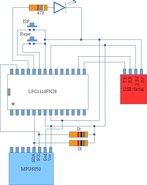
This project demonstrates how you might interface the MPU6050 accelerometer/gyroscope module with the LPC1114. The code is a little complex as two interrupt service routines are used: one for the I2C interface and one for the UART interface. A further complexity is the asynchronous nature of both communications interfaces. A “state-recorder” was used to help track down bugs during development. Further details and downloads are available here
Low power sensor node follow up.
I finally achieved a target run time (estimated) of a year on a couple of AAA batteries for the NRF24L01 and the STM32F030. The current flow is mostly zero but once a second the MCU wakes up and transmits a message leading to a current waveform like this:
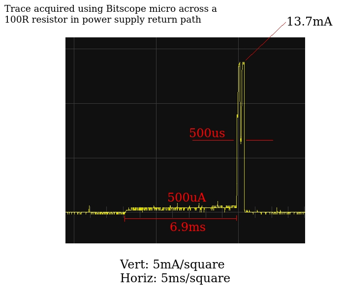
The best estimate I can come up with for the average current flow puts it below 100uA which should allow very long run times off a pair of AAA batteries.
Code, circuits, results and further discussion is here
Using the RTC on the STM32F0 (STM32F030) value line discovery board
I’ve been trying to get the RTC going on the STM32F030Discovery board (The STM32 F0 Value Line Discovery board) with the aim of reducing average current consumption. After quite a struggle I finally figured it out. Demo code can be downloaded here. Next step: apply this a the STMF030/NRF24L01 node
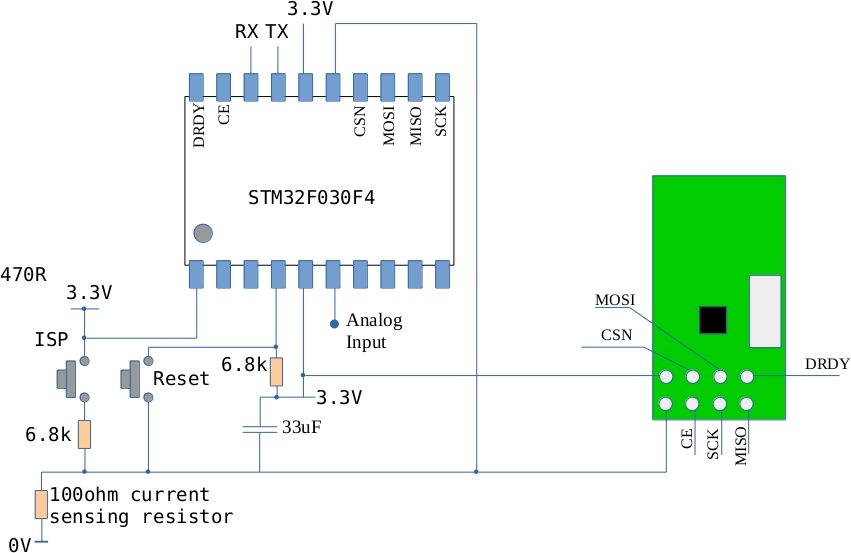
Reducing power consumption on the STM32F030 and the NRF24L01
The original code I used for this circuits consumed as much as 20mA when running. This is way too much for a battery powered application. The main power consumers are of course the NRF24L01 radio and the MCU. The radio current can be reduced significantly if its RF section is turned off when not in use. The scenario I have in mind for this device is that it would periodically measure an analogue signal and transmit the result to a base station. This requires the radio to be on for a very short time (the length of time it takes to send a packet). The remainder of the time, the radio can be in low power standby mode.
The MCU power consumption can be reduced by entering sleep mode and waking up periodically to measure and transmit data. Originally I tried to use the ARM Cortex SysTick interrupt however its power consumption was still too high. In an attempt to reduce power consumption, the AHB Bus clock was reduced (using the prescaler) but it seems that the SysTick timer stops running when you do this. This approach was abandoned and one of the other timers was used to periodically wake the MCU up. The ARM Cortex M0 can enter into two different types of deep sleep mode: regular and deep. In regular sleep mode, the CPU core is stopped but the peripherals continue to receive a clock signal. In deep sleep mode all clocks stop (except the RTC clock – more on this in a later post). If no clocks are running then the periodic wake-up timer will not run either so deep sleep is out for now. This is not too bad a situation however as the regular timers will run quite happily if the AHB bus clock speed is reduced.
The solution
The MCU starts up and, configures ports, ADC and a timer. It also initializes the radio. A measurement is taken and the MCU is put into low power mode. In this mode the MCU core is stopped and the AHB bus clock is reduced to 8MHz/512 ( 15625Hz) and most peripherals are disabled. This greatly reduces power consumption. The timer is configured to generate an interrupt every 5 seconds. The interrupt wakes the MCU core up which accelerates back up to 8MHz, re-enables the various peripherals, takes a measurement, sends data and then goes back to sleep.
Current consumption
The current consumption during sleep drops to 0.57mA (lets call this the quiescent current). The current while awake is difficult to measure using a multimeter however its duty cycle is very low so over time its affect on battery life is probably a lot less than the quiescent current.
Battery life
If the circuit is powered off two AAA batteries in series (3V in total) each with a capacity of 750mAh (typical) then I would expect this circuit to run for about 2 months (it is currently running at 3.3V so the drop to 3V should reduce current a little).
Possible improvements
The radio module is powered down to its lowest level when not in use so without tinkering with the surface mount resistors I can’t see this current decreasing much. It may be possible to reduce the MCU current using the build-in RTC circuit. This has an independent low speed clock that continues to run while the MCU is in a deep sleep mode. There are potentially big savings here!
Code
The current state of the code can be downloaded here – it includes the Intel Galileo node.js code that receives data from the circuit.
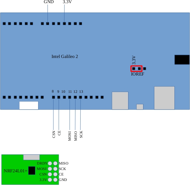
NRF24L01 Channel scan
I used an NRF24L01+ attached to an Intel Galileo Gen2 to do an RF channel scan in an effort to identify a “good” choice for a channel that will best avoid interference. The program repeatedly changes channel and monitors the Received Power Detect Bit (Register 9). The program ran for and hour and counted up the number of times the RPD bit was 1 for each of the 128 channels and produced an output like this:
0 0 0 0 0 0 1 0 0 0 1 0 0 1 1 0
1 0 0 0 1 0 1 1 0 2 1 0 0 0 0 1
0 0 0 0 0 0 0 1 0 1 1 0 1 0 0 0
0 0 1 0 0 1 3 6 3 2 4 9 4 7 12 5
4 7 2 3 7 5 1 3 0 0 0 0 0 0 0 0
0 0 0 0 0 0 0 0 0 0 0 0 0 0 0 0
0 0 0 0 0 0 0 0 0 0 0 0 0 0 0 0
0 0 0 0 0 0 0 0 0 0 0 0 0 0 0 0
Each step across the output array represents a 1MHz step in frequency. The start frequency is 2400MHz. The value ’12’ occurs at a frequency of 2462MHz. This corresponds to Wifi Channel 11 – a fact confirmed by doing a Wifi Channel scan on my laptop which showed two Wifi access points operating at this frequency.
It is worth noticing that there is not much happening beyond 2471MHz. This is probably because Wifi stops around here (at least in Europe). So is this the answer – simply stay outside the Wifi bands? In Europe, the Wifi bands range from 2412MHz to 2472MHz so maybe the best NRF24L01 channels are less than 12 and greater than 72. Time will tell….
Code is below (node.js)
// NRF24L01+ demo in javascript for the Intel Galileo Gen 2
// Author: Frank Duignan.
// Updates posted on http://ioprog.com and http://eleceng.dit.ie/frank

var PAYLOAD_LENGTH=10
var SOURCE_ADDRESS=([8,0,5,8,6]);
var DESTINATION_ADDRESS=([0x0a,1,1,1,4]);
/******* Low level setup (configure I/O etc *******/
var m=require('mraa');
console.log('MRAA version: ' + m.getVersion());
// configure SPI for 1MHz operation
var SPI=new m.Spi(0);
SPI.frequency(1000000);
// Set up CE and CSN pins for the NRF24L01
// These will be directly controlled by software NOT the SPI hardware
var CEPin=new m.Gpio(9);
var CSNPin=new m.Gpio(8);
CEPin.dir(m.DIR_OUT);
CSNPin.dir(m.DIR_OUT);
CEPin.write(0);
CSNPin.write(1);
// Global variable that is updated during each SPI transaction
var NRFStatus;


// NRF Functions follow
function NRFinit()
{
	NRFWriteRegister(0,0);			// Clear out config
	NRFWriteRegister(1,3);			// enable auto ack in P0 and P1
	NRFWriteRegister(4,0x24);		// 750us between retries, 4 retries
	NRFWriteRegister(2,3);			// enable data pipe 0 and 1
	NRFWriteRegister(3,3);			// 5 byte addressing
	NRFWriteRegister(0x05,5); 		// select channel 5
	NRFWriteRegister(0x06,0x06); 	// select 1Mbps, maximum power
	NRFWriteRegister(0x07,0x70); 	// clear status flags
	NRFWriteRegister(0x11,0);		// Auto ack in pipe 0
	NRFWriteRegister(0x12,PAYLOAD_LENGTH);	// set payload length
	NRFWriteCE(1);
	NRFEnableRXMode();				// start listening
}
function delay(howlong)
{
	howlong = howlong / 2; // yields approx 1us timebase
	while(howlong > 0)
	{
		howlong = howlong -1 ;
	}
}
function NRFWriteCE(Value)
{
	if (Value)
		CEPin.write(1)
	else
		CEPin.write(0)

}
function NRFWriteCSN(Value)
{
	if (Value )
		CSNPin.write(1);
	else
		CSNPin.write(0);
}

function transferSPI(data)
{
	return SPI.writeByte(data);
}

function NRFReadRegister(RegNum)
{
	var ReturnValue=0;
	NRFWriteCSN(0);
	if (RegNum < 0x20)
	{
		NRFStatus = transferSPI(RegNum); // update status after CSN goes low
		ReturnValue = transferSPI(0xff); // Send dummy byte to generate clocks
	}
	else
	{
		ReturnValue = -1;
	}
	NRFWriteCSN(1);
	return ReturnValue;
}

function NRFWriteRegister(RegNum, Value)
{
	var ReturnValue=0;
	NRFWriteCSN(0);
	if (RegNum < 0x20)
	{
		NRFStatus = transferSPI(0x20+RegNum); // update status after CSN goes low
		ReturnValue = transferSPI(Value);	  // Write byte to target
	}
	else
	{
		ReturnValue = -1;
	}
	NRFWriteCSN(1);
	return ReturnValue;
}
function NRFFlushTX()
{
	NRFWriteCSN(0);
	NRFStatus = transferSPI(0xe1); // Send Flush TX command
	NRFWriteCSN(1);
}
function NRFFlushRX()
{
	NRFWriteCSN(0);
	NRFStatus = transferSPI(0xe2); // Send Flush RX command
	NRFWriteCSN(1);
}

function NRFSetRXAddress0(AddressLength, Address)
{
	var index;
	switch (AddressLength) {
		case 3 : {
			NRFWriteRegister(3,1); // 3 byte address length
			break;
		}
		case 4 : {
			NRFWriteRegister(3,2); // 4 byte address length
			break;
		}
		case 5 : {
			NRFWriteRegister(3,3); // 5 byte address length
			break;
		}
		default: {
			return -1; // invalid address length
		}
	}
	NRFWriteCSN(0);
	NRFStatus = transferSPI(0x20+0x0a); // start write to RX_P0_Pipe address
	for (index = 0; index < AddressLength; index++)
	{
		NRFStatus = transferSPI(Address[index]);
	}
	NRFWriteCSN(1);
}
function NRFSetRXAddress1(AddressLength, Address)
{
	var index;
	switch (AddressLength) {
		case 3 : {
			NRFWriteRegister(3,1); // 3 byte address length
			break;
		}
		case 4 : {
			NRFWriteRegister(3,2); // 4 byte address length
			break;
		}
		case 5 : {
			NRFWriteRegister(3,3); // 5 byte address length
			break;
		}
		default: {
			return -1; // invalid address length
		}
	}
	NRFWriteCSN(0);
	NRFStatus = transferSPI(0x20+0x0b); // start write to RX_P1_Pipe address
	for (index = 0; index < AddressLength; index++)
	{
		NRFStatus = transferSPI(Address[index]);
	}
	NRFWriteCSN(1);
}
function NRFGetRXAddress( MaxAddressLength,  Address)
{
	var index;
	var actual_length;
	actual_length = NRFReadRegister(3);
	actual_length = actual_length + 2;
	if (actual_length > MaxAddressLength)
		return -1;
	NRFWriteCSN(0);
	NRFStatus = transferSPI(0x0a); // start read from RX_P0_Pipe address
	for (index = 0; index < actual_length; index++)
	{
		Address[index] = transferSPI(0xff);
	}
	NRFWriteCSN(1);
	return(0);
}
function NRFSetTXAddress(AddressLength, Address)
{
	var index;
	switch (AddressLength) {
		case 3 : {
			NRFWriteRegister(3,1); // 3 byte address length
			break;
		}
		case 4 : {
			NRFWriteRegister(3,2); // 4 byte address length
			break;
		}
		case 5 : {
			NRFWriteRegister(3,3); // 5 byte address length
			break;
		}
		default: {
			return -1; // invalid address length
		}
	}
	NRFWriteCSN(0);
	NRFStatus = transferSPI(0x20+0x10); // start write to TX address
	for (index = 0; index < AddressLength; index++)
	{
		transferSPI(Address[index]);
	}
	NRFWriteCSN(1);
	return(0);
}

function NRFGetTXAddress(MaxAddressLength, Address)
{
	var index;
	var actual_length;
	actual_length = NRFReadRegister(3);
	actual_length = actual_length + 2;
	if (actual_length > MaxAddressLength)
		return -1;
	NRFWriteCSN(0);
	NRFStatus = transferSPI(0x10); // start read from TX address
	for (index = 0; index < actual_length; index++)
	{
		Address[index] = transferSPI(0xff);
	}
	NRFWriteCSN(1);
	return(0);
}
function NRFEnableTXMode()
{
	NRFWriteRegister(0,0x0a); // enable CRC, power up
}
function NRFEnableRXMode()
{
	NRFWriteRegister(0,0x0b); // enable CRC, power up, RX mode
}
function NRFWriteData(Length, Data)
{
	var index;
	if (Length > 32)
		return -1; // too long
	NRFWriteCE(0);
	NRFWriteRegister(0x07,0x70); // clear RX_DR,TX_DS,MAX_RT bits
	NRFEnableTXMode();
	NRFWriteCSN(0);
	NRFStatus = transferSPI(0xa0); // start write to TX buffer
	for (index = 0; index < Length; index++)
	{
		transferSPI(Data[index]);
	}
	NRFWriteCSN(1);
	NRFWriteCE(1);
	console.log("Sending..");
	NRFEnableRXMode();
}
function NRFReadData(MaxLength,Data)
{ // data is assumeed to be in data pipe 1
	var available_bytes;
	var index;
	var Length;
	available_bytes=NRFReadRegister(0x12); // find out how many bytes are available in P1
	if (available_bytes == 0)
		return 0;
	NRFWriteCSN(0);
	NRFStatus = transferSPI(0x61); // start read from RX buffer
	if (available_bytes > MaxLength)
		Length = MaxLength;
	else
		Length = available_bytes;
	for (index = 0; index < Length; index++)
	{
		Data[index]=transferSPI(0xff);
	}
	NRFWriteCSN(1);
	return Length;
}
function printRegisters()
{
	var regnum;
	for (regnum = 0;regnum < 0x20; regnum++)
	{
		var hexstring= NRFReadRegister(regnum).toString(16);
		console.log(regnum.toString(16) + " : " + hexstring);
	}
}
/* The main body of the program follows.
 * The NRF is initialized with correct addresses etc and is periodically
 * polled to see if there is any data available in the RX FIFO
 * If there is data it is read and a byte is sent back
*/
var ChannelTraffic = new Buffer(128);
function poll()
{
	// check to see if there is any received data
	var cd=NRFReadRegister(0x09);
	//console.log(Channel+":"+cd);
	NRFWriteRegister(0x05,Channel); 		// select channel
	NRFWriteCE(1);
	NRFEnableRXMode();
	NRFWriteCE(0);
	if (cd)
		ChannelTraffic[Channel] = ChannelTraffic[Channel]+1;
	Channel++;
	if (Channel > 127)
	{
		Channel = 1;
		var row=0;
		var column=0;
		while(row < 8)
		{
			column = 0;
			while(column < 16)
			{
				process.stdout.write(ChannelTraffic[row*16+column]+" ");
				column++;
			}
			console.log(" ");
			row++;

		}
		console.log("-----------------------------------------");
		//console.log(ChannelTraffic);
	}
	setTimeout(poll,50);
}


var Channel=0;
while(Channel < 128)
{
	ChannelTraffic[Channel]=0;
	Channel++;
}
Channel = 0;
NRFinit();
NRFSetRXAddress0(5,DESTINATION_ADDRESS); // set auto ack address = destination
NRFSetTXAddress(5,DESTINATION_ADDRESS);	 // set destination address
NRFSetRXAddress1(5,SOURCE_ADDRESS);		 // set source address
console.log("Switching to RX mode");
NRFFlushTX();
NRFFlushRX();
NRFEnableRXMode();
NRFWriteRegister(0x05,Channel); 		// select channel
NRFWriteCE(1);
printRegisters();
poll();
Interfacing an STM32F030 MCU to the NRF24L01+ radio module

The NRF24L01+ is a nice low cost radio module that works well with the STM32F030 MCU. I’ve begun documenting my work on this over at eleceng.dit.ie
A radio link between the LPC1114 and an Intel Galileo Gen 2 using the NRF24L01
I finally got a link set up between an Intel Galileo Gen 2 and an LPC1114 using the very low cost and low energy NRF24L01 radio modules. The interface code is written from the ground up and is in C for the LPC1114 and javascript for the Galileo. Both code bases were developed in parallel so function names and semantics are common to both.

Full details are available here:
http://eleceng.dit.ie/frank/arm/BareMetalLPC1114/nrf24l01/index.html
Setting up arm-none-eabi-gcc on Ubuntu 15.04
I went and downloaded gcc for arm from https://launchpad.net/gcc-arm-embedded/+download. I extracted it to /usr/local on a fresh Ubuntu 15.04 install. This creates a directory with the following name
/usr/local/gcc-arm-none-eabi-4_9-2015q2
I find this a bit cumbersome so I usually do a symbolic link to /usr/local/gcc-arm-none-eabi as follows:
ln -s /usr/local/gcc-arm-none-eabi-4_9-2015q2 /usr/local/gcc-arm-none-eabi
Anyway, having done all of that, when I tried to use the compiler I got an error message as follows:
frank@voyager:/usr/local$ arm-none-eabi-gcc –version
bash: /usr/local/gcc-arm-none-eabi/bin/arm-none-eabi-gcc: No such file or directory
This usually means that there is a missing dll that the program relies on. My installation is a 64 bit one however the gcc-arm compiler from launchpad.net is compiled for 32 bit systems. The linux program loader was complaining it couldn’t find the bit versions of libc. This can be fixed as follows:
sudo apt-get install lib32z1 lib32ncurses5
This installs a 32 version of libc (alongside the 64 bit one). The compiler now works fine.
I added the compiler directory to my path by editing the “.profile” file in my home directory. The .profile file now looks like this
# ~/.profile: executed by the command interpreter for login shells.
# This file is not read by bash(1), if ~/.bash_profile or ~/.bash_login
# exists.
# see /usr/share/doc/bash/examples/startup-files for examples.
# the files are located in the bash-doc package.

# the default umask is set in /etc/profile; for setting the umask
# for ssh logins, install and configure the libpam-umask package.
#umask 022

# if running bash
if [ -n "$BASH_VERSION" ]; then
    # include .bashrc if it exists
    if [ -f "$HOME/.bashrc" ]; then
	. "$HOME/.bashrc"
    fi
fi

# set PATH so it includes user's private bin if it exists
if [ -d "$HOME/bin" ] ; then
    PATH="$HOME/bin:$PATH"
fi
PATH="$PATH:/usr/local/gcc-arm-none-eabi/bin"
The last line extends the PATH environment variable so that it now points to the directory containing arm-none-eabi-gcc. Each time you login, the .profile file is read and the PATH is set as shown. (if you want the PATH to take immediate effect in the terminal you are currently working in do this: source ~/.profile )
The North Star project
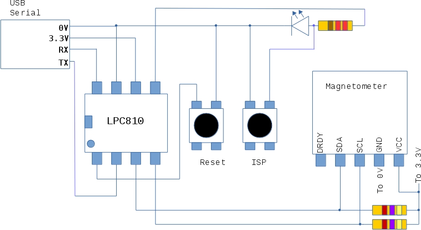
This project uses an LPC810 and an HMC5883L magnetometer. If the project board points north a blue LED lights up. Full code is available here:
http://eleceng.dit.ie/frank/arm/BareMetalLPC810/northstar/
LPC810 Post ISP pin assignment.
I was curious about the pin assignment on the LPC810 (DIP8) after an ISP load and boot cycle. Here are the values that turned up
PINASSIGN0 FFFF0004
PINASSIGN1 FFFFFFFF
PINASSIGN2 FFFFFFFF
PINASSIGN3 FFFFFFFF
PINASSIGN4 FFFFFFFF
PINASSIGN5 FFFFFFFF
PINASSIGN6 FFFFFFFF
PINASSIGN7 FFFFFFFF
PINASSIGN8 FFFFFFFF
PINENABLE0 000001B3
PIO0_0 01010101
PIO0_1 01010101
PIO0_2 00000101
PIO0_3 01010101
PIO0_4 00000101
PIO0_5 00000000
The value in PINASSIGN0 show that TXD0 is on PIO0_4 and RXD0 is on PIO0_0.
The other PINASSIGN registers are at their default values as is PINENABLE0
