A long time ago I posted an example that used the SysTick timer in the STM32F0Discovery board. This had a bug! A reader (Dale Wheat) kindly pointed out that it had a problem with the way the bits were set in the STK_CSR register. Anyway, I’ve corrected the bug and posted revised code which can be found here. Thanks Dale!
Uncategorized
9 DOF on the STM32L476 Discovery board
The STM32L476 Discovery board has an LSM303 Accelerometer/Compass IC and an L3GD20 gyroscope attached to the MCU using an SPI bus and some chip select lines. I wanted to experiment with them with a view to putting together a balancing robot. Supporting code for the following was needed for this:
- an SPI interface
- the LSM303
- the L3GD20
- serial communications
- periodic interrupts to pace data capture
Rather than build a complex Makefile I went with a simple shell script (or batch file if you prefer) with the following commands:
arm-none-eabi-gcc -static -mthumb -g -mcpu=cortex-m4 *.c -T linker_script.ld -o main.elf -nostartfiles
arm-none-eabi-objcopy -g -O binary main.elf main.bin
Note: your PATH environment variable must include the directory where arm-none-eabi-gcc is located.
The resulting main.bin file can then be copied to the virtual disk presented by the mbed interface on the STM32L476 discovery board. (The program waits for you to press the centre joystick button before starting).`
Serial communications is carried out over the built-in ST-Link USB-Serial emulator so no additional hardware is needed (9600,n,8,1).
Code is available over here
Serial communications on the STM32L476 discovery board
The STM32L476 discovery board has a useful built-in USB/Serial emulator in the ST-Link debug interface. This allows you to exchange data with the board without any extra hardware. Sample code is over here.
Discovering the STM32L476G Discovery board
I have begun working the STM32L476 Discovery board taking a “Bare metal” approach. It is a great board with some nice peripherals. Code will be built up over time over here
To compile this code you need the a cross compiler for ARM that works on your system. You don’t need a fancy debugger or complicated software : the board has an mbed interface so you can just copy the program you develop to the board as if it was a removable disk.
Sending encrypted data from an MSP432 to a python script
This post shows how you might send encrypted data over as serial communications port. The example was written for the MSP432 using the Energia environment. It uses AES128 ECB encryption using a pre-shared, hard coded (bad practice) key. The example generates a simple text message with a counter that counts from 0 to 255 repeatedly. The message is encrypted and sent as a HEX string (so I can read it) over a serial port. The receiver is a python script that decrypts the data and displays it to the screen. The code was developed in a Linux environment but should work fine in other operating systems – you will need to change the path for the serial port.
This example does not deal with the thorny issue of key distribution.
Energia code
#include <msp432.h>
#include <stdio.h>
/*   Serial communications with AES 128 ECB encryption
     Data sent in ASCII hex (e.g. the value 0x02 will
     be sent as the string "02".  Transmitting in this
     way allows us monitor the messages using a simple
     serial monitor.  It also allows us use the
     Serial.print and Serial.println methods without
     worrying about data values that are zero (which
     will be interpreted as end of string markers by the
     Serial library routines.  Of course this is less
     efficient but it will hopefully be instructive.
*/

// Data block size (in bytes)
#define BLOCKSIZE 16

const char key[] = "8d2e60365f17c7df1040d7501b4a7b5a";
char plaintext[BLOCKSIZE];
///const char MSG[] = "Mary had a little lamb"; //  "Mary had a little lamb";
// the setup routine runs once when you press reset:
void setup() {
  Serial.begin(38400);
}
int Counter;
// the loop routine runs over and over again forever:
void loop() {
  sprintf(plaintext,"Counter=%d",Counter);
  Counter++;
  if (Counter > 255)
    Counter = 0;
  SendEncryptedMessage(plaintext, sizeof(plaintext) );
  delay(1000);
}

uint32_t ByteStringToNumber(const char *Str)
{
  uint32_t UpperNibble = 0;
  uint32_t LowerNibble = 0;
  if (Str[0] > '9')
    UpperNibble = (  Str[0] | 32 ) - 'a' + 10; // ensure lower case, remove hex 'a' and offset by 10
  else
    UpperNibble = ( Str[0] - '0');
  if (Str[1] > '9')
    LowerNibble = (  Str[1] | 32 ) - 'a' + 10; // ensure lower case, remove hex 'a' and offset by 10
  else
    LowerNibble = ( Str[1] - '0');
  return (UpperNibble << 4) + LowerNibble;
}
void setKey(const char * keystr)
{
  // The key will take the form of a 32 character ASCII string produced
  // by a tool like openssl.
  // This routine will extract the bytes from the string and store them
  // in the AES accelerator
  int Index;
  uint32_t KeySection;
  uint8_t *Ptr = (uint8_t *)(&AESAKEY);
  for (Index = 0; Index < 16; Index++)
  {
    KeySection = ByteStringToNumber(keystr + Index * 2);
    *Ptr = (uint8_t) KeySection;
  }
}

void SendEncryptedMessage(const char *Payload, unsigned int len)
{
  // Send the payload over the encrypted channel
  // Message is padded with zeros if it is not a multiple of BLOCKSIZE
  unsigned int BlockIndex = 0;
  unsigned int TotalByteCount = 0;
  uint8_t PlainTextBuffer[BLOCKSIZE];
  uint8_t CryptoText[BLOCKSIZE];
  volatile uint8_t *InputDataRegister;
  volatile uint8_t *OutputDataRegister;

  AESACTL0 = 0; // Set the AES engine into encryption mode
  setKey(key);  // Must set key after changing mode

  while (TotalByteCount < len)
  {
    BlockIndex = 0;
    while (BlockIndex < BLOCKSIZE)
    {
      if (TotalByteCount < len)
        PlainTextBuffer[BlockIndex] = Payload[TotalByteCount];
      else
        PlainTextBuffer[BlockIndex] = 0;
      BlockIndex++;
      TotalByteCount++;
    }
    InputDataRegister = (uint8_t *)&AESADIN;
    for (BlockIndex = 0; BlockIndex < BLOCKSIZE; BlockIndex++)
      *InputDataRegister = PlainTextBuffer[BlockIndex];
    delay(1);

    OutputDataRegister = (uint8_t *)&AESADOUT;
    for (BlockIndex = 0; BlockIndex < 16; BlockIndex++)
      CryptoText[BlockIndex] = *OutputDataRegister;

    for (BlockIndex = 0; BlockIndex < BLOCKSIZE; BlockIndex++)
    {
      if (CryptoText[BlockIndex] < 16)
        Serial.print("0"); // send leading zeros for values < 16
      Serial.print(int(CryptoText[BlockIndex]), HEX);
    }

    Serial.println(""); // Send a line feed after each block
  }

}
Python code
# This python script receives encrypted data over the serial port
# The encryption method is AES128, ECB and the key is hardcoded into
# sender and receiver
# Expected received data format:
# ASCII-HEX 32 characters (representing 16 bytes or 128 bits) followed by
# CR LF (\r\n)

from Crypto.Cipher import AES
import serial as ser;
import binascii
port=ser.serial_for_url("/dev/ttyACM0") # CHANGE THIS TO SUIT YOUR SITUATION!!!
port.baudrate=38400
key = binascii.unhexlify('8d2e60365f17c7df1040d7501b4a7b5a')
IV = 16 * '\x00' # set inital vector (or state) to 0
mode = AES.MODE_ECB # Electronic Code Book encryption used
encryptor = AES.new(key, mode, IV=IV)
while (1):
    ciphertext=port.read_until()
    if len(ciphertext)==34:      # got a full packet?
        ciphertext=ciphertext[:32] # trim off CR LF
        # convert to actual values rather than hex string
        ciphertext=binascii.unhexlify(ciphertext)
        plaintext = encryptor.decrypt(ciphertext) # decrypt
        print(plaintext)
Energia and the MSP432 AES encryption engine
I’ve been trying to get matching results between the TI-MSP432’s encryption engine and a python equivalent on my laptop. It has been a bit frustrating but I think I’ve got it. The main cause of my frustration is that the AES registers are declared as if they represented 16 bit quantities and so the compiler was generating 2 byte writes to the registers. For example, the AESAKEY register is declared in msp432p401r_classic.h as follows:
#define AESAKEY (HWREG16(0x40003C06))
This messed up the engine’s state when I wanted to write bytes. Anyway, it works now and here is some Energia code that outputs the same answer as a python script (which is included in the comments). The code needs a little work and I hope to set up an encrypted link between the MSP432 and the PC over the UART.
#include <msp432.h>
/*key and message obtained from NIST test vectors in http://csrc.nist.gov/groups/STM/cavp/documents/aes/AESAVS.pdf */
/* Using AES 128 ECB Encryption */
/* Tested against the following python code:

# This produces the same answer as http://aes.online-domain-tools.com/
# but not the same as NIST test vector for ECB
from Crypto.Cipher import AES
import binascii
key = binascii.unhexlify('8d2e60365f17c7df1040d7501b4a7b5a')
IV = 16 * '\x00'
mode = AES.MODE_ECB
encryptor = AES.new(key, mode, IV=IV)
text = binascii.unhexlify('59b5088e6dadc3ad5f27a460872d5929')
#text=b'Plain text msg  '
ciphertext = encryptor.encrypt(text)
print(binascii.hexlify(ciphertext))

 */
const char key[]="8d2e60365f17c7df1040d7501b4a7b5a";
const char testmsg[]="59b5088e6dadc3ad5f27a460872d5929";
uint32_t ByteStringToNumber(const char *Str)
{
  uint32_t UpperNibble = 0;
  uint32_t LowerNibble = 0;
  if (Str[0] > '9')
    UpperNibble = (  Str[0] | 32 ) - 'a' + 10; // ensure lower case, remove hex 'a' and offset by 10
  else
    UpperNibble = ( Str[0] - '0');
  if (Str[1] > '9')
    LowerNibble = (  Str[1] | 32 ) - 'a' + 10; // ensure lower case, remove hex 'a' and offset by 10
  else
    LowerNibble = ( Str[1] - '0');
  return (UpperNibble << 4) + LowerNibble;
}
void setKey(const char * keystr)
{
  // The key will take the form of a 32 character ASCII string produced
  // by a tool like openssl.
  // This routine will extract the bytes from the string and store them
  // in the AES accelerator
  int Index;
  uint32_t KeySection;
  uint8_t *Ptr = (uint8_t *)(&AESAKEY);
  Serial.println("Setting the following key: ");
  for (Index = 0; Index < 16; Index++)
  {

    KeySection = ByteStringToNumber(keystr+Index*2);
    Serial.print(KeySection,HEX);
    Serial.print(" ");
    *Ptr = (uint8_t) KeySection;

  }
  Serial.println("");
  printAESRegisters();
}
void encryptBlock(const char *plain_text, char *crypto_text, uint32_t len)
{
  // Encrypts a 128 bit (16 byte) block of text
  int Index = 0;
  uint8_t Dummy = 0;
  uint32_t Section;
  volatile void *Ptr;
  // select encrypt mode
  AESACTL0 = 0;//0xfffc;
  setKey(key);
  Ptr = &AESADIN;
  Serial.println("Encrypting the following:" );
  for (Index = 0; Index < 16; Index++)
  {

    Section = ByteStringToNumber(plain_text+Index*2);
    Serial.print(Section,HEX);
    Serial.print(" ");
    *((uint8_t *)Ptr) = (uint8_t)Section;
  }
  Serial.println(" ");
  delay(4);
  //while ( (AESACTL0 & (1 << 8) )==0); // wait for ready flag
  Ptr = &AESADOUT;
  for (Index = 0; Index < 16; Index ++)
  {
      crypto_text[Index] =  *((uint8_t *)Ptr);
  }
}


void printAESRegisters()
{
  Serial.print("AESASTAT: ");
  Serial.print(String(AESASTAT,16));
  Serial.print(", AESACTL0: ");
  Serial.print(String(AESACTL0,16));
  Serial.print(",  AESACTL1: ");
  Serial.println(String(AESACTL1,16));
}


// the setup routine runs once when you press reset:
void setup() {
  Serial.begin(38400);
}
char CryptoText[17];
// the loop routine runs over and over again forever:
void loop() {
  int Index;
  CryptoText[16]=0;
  AESACTL0 = 0;

  encryptBlock(testmsg,CryptoText,16);
  Serial.println("Just encrypted");
  printAESRegisters();
  Serial.println("Crypto Text:");

  for (Index = 0 ; Index < 16; Index ++ )
  {
    Serial.print(int(CryptoText[Index]),HEX);
    Serial.print(" ");
  }
  Serial.println(" ");
  Serial.println(CryptoText);
  Serial.println("--------------------------------");

  delay(501);
}
Command line compiling
A student asked how to use the standard C libraries with one of my examples recently. He wanted to know how to use string functions such as strcat, strcpy and so on. This isn’t something I had tried before because my goal was to expose the lower level details of hardware I/O. Anyway, having fiddled around a bit on the command line I came up with this command for buidling code for the STM32L011 nucleo board
arm-none-eabi-gcc -static -mthumb -mcpu=cortex-m0plus main.c init.c serial.c -T linker_script.ld -o main.elf -nostartfiles
Breaking this down:
arm-none-eabi-gcc: Your cross compiler. Your PATH environment variable should include the directory this lives in.
-static: Don’t use DLL’s (run-time linking) i.e. include the library function code in the final executable image.
-mthumb: Generate thumb code rather than ARM code.
-mcpu=cortex-m0plus: The STM32L011 has a Cortex M0+ CPU
The list of C files
-T linker_script.ld: Use this linker script to define memory regions when building the output executable image.
-o main.elf: name the output file main.elf
–nostartfiles: Don’t include “standard” start and stop functions. The code includes our own custom start-up code
I wanted to be able to dump the output file onto the virtual disk emulated by the nucleo board. This is done as follows:
arm-none-eabi-objcopy -O binary main.elf main.bin
This creates a raw binary program image which can be dropped on to the virtual disk.
The code was based a previous serial example for the STM32L011. The main.c file is replaced with this:
/*
 * Serial: serial i/o routines for the STM32L011
*/


#include "stm32l011.h"
#include "serial.h"
#include <string.h>
void delay(int);

void delay(int dly)
{
  while( dly--);
}

void initClockHSI16()
{
    // Use the HSI16 clock as the system clock - allows operation down to 1.5V
        RCC_CR &= ~BIT24;
        RCC_CR |= BIT0; // turn on HSI16 (16MHz clock)
        while ((RCC_CR & BIT2)==0); // wait for HSI to be ready
        // set HSI16 as system clock source
        RCC_CFGR |= BIT0;
}
void configPins()
{
	// Enable PORTB where LED is connected
	RCC_IOPENR |= BIT1;
	GPIOB_MODER |= BIT6; // make bit3  an output
	GPIOB_MODER &= ~BIT7; // make bit3  an output
}
const char Str1[]="Hello ";
const char Str2[]="World\r\n";
char CombinedString[50];
int main()
{
        uint32_t Counter=0;
	initClockHSI16();
	configPins();
        initUART(9600);
	CombinedString[0]=0;
        CombinedString[49]=0;

	while(1)
	{
		GPIOB_ODR |= BIT3;
		delay(2000000);
		GPIOB_ODR &= ~BIT3;
		delay(2000000);
                strcpy(CombinedString,Str1);
                strcat(CombinedString,Str2);
                eputs(CombinedString);
                eputs("\r\n");
	}
	return 0;
}
Energia, MSP432 delays and serial data corruption.
Here is my Energia MSP432 Code:
// the setup routine runs once when you press reset:
void setup() {
  Serial.begin(38400);
}

// the loop routine runs over and over again forever:
void loop() {
  Serial.println("Hello World");
  delay(500);
}
I expected this to produce a stream of “Hello World” strings. It didn’t! I got this instead:
Hello World��
Hello World��
Hello World��
Hello World��
Hello World��
Hello World��
I discovered that if I change the delay to 501, I got an output like this:
Hello World
Hello World
Hello World
Hello World
Hello World
Hello World
How could a millisecond make such a difference? The answer lies in the way delay is implemented in the MSP432 wiring library. Sections of this library are shown below (file is wiring.c). The short answer to my problem is this:
If the delay in milliseconds is a divisible by 250 the library puts the MSP432 into a deep sleep and lets the watchdog timer wake it up 250ms later. When in such a sleep, the state of the TX pin is high impedance so it is susceptible to noise (hence the junk after Hello World).
If the delay is not divisible by 250 then the CPU is not put into a deep sleep and the TX pin is maintained at a known state.
This “feature” was found in Energia 1.6.10E18 and on a Rev 1.0 MSP432 board. It could probably be fixed by using a pull-up resistor on the TX line.
So, if you see this effect in your program just add one to your delays 🙂
void delay(uint32_t milliseconds)
{
    if (milliseconds == 0) {
        Task_yield();
        return;
    }

    switch (delayMode) {
        /* using Timer_A, check for opportunity to transition to WDT */
        case 0:
            if ( (milliseconds >= 250) && (milliseconds % 250) == 0) {
                delayMode = 1;
                switchToWatchdogTimer();
            }
            else {
                delayMode = 2;
                switchToTimerA();
            }
            break;
        /* using WDT, check for need to transition to Timer_A */
        case 1:
            if ( (milliseconds >= 250) && (milliseconds % 250) == 0) {
                /* stay in mode 1 */
            }
            else {
                /* switch to Timer_A and never look back */
                delayMode = 2;
                switchToTimerA();
            }
            break;
        /* always using Timer_A */
        case 2:
            break;
    }

    /* timeout is always in milliseconds so that Clock_workFunc() behaves properly */
    Task_sleep(milliseconds);
}

/*
 *  ======== switchToWatchdogTimer ========
 *
 *  Use 250ms watchdog timer interrupt to drive the Clock tick
 *  Stop the default Timer_A then start the watchdog timer.
 */
static void switchToWatchdogTimer()
{
    Clock_TimerProxy_Handle clockTimer;
    static Hwi_Handle wdtHwi = NULL;

    /* Stop Timer_A currrently being used by Clock */
    clockTimer = Clock_getTimerHandle();
    Clock_TimerProxy_stop(clockTimer);

    MAP_WDT_A_holdTimer();

    if (wdtHwi == NULL) {
        /* Create watchdog Timer Hwi */
        wdtHwi = Hwi_create(19, clockTickFxn, NULL, NULL);

        /* set WDT to use 32KHz input, 250ms period */
        MAP_WDT_A_initIntervalTimer(WDT_A_CLOCKSOURCE_XCLK, WDT_A_CLOCKITERATIONS_8192);
    }

    /* remove DEEPSLEEP0 constraint left from TimerA usage */
    Power_releaseConstraint(PowerMSP432_DISALLOW_DEEPSLEEP_0);

    /* don't allow deeper than DEEPSLEEP1 */
    Power_setConstraint(PowerMSP432_DISALLOW_DEEPSLEEP_1);

    /* Start watchdog Timer */
    MAP_WDT_A_clearTimer();
    MAP_WDT_A_startTimer();

    /* hence, Clock_tick() will be called from 250ms watchdog timer interrupt */
}

/*
 *  ======== switchToTimerA ========
 *
 *  Use 1ms Timer_A interrupt to drive the Clock tick
 *  By default, the Timer_A Hwi object has already been
 *  statically created and configured to call Clock_tick().
 *  Simply stop the watchdog timer and restart the Timer_A.
 */
static void switchToTimerA()
{
    Clock_TimerProxy_Handle clockTimer;

    /* Stop watchdog Timer */
    MAP_WDT_A_holdTimer();

    /* remove DEEPSLEEP1 constraint left from watchdog usage */
    Power_releaseConstraint(PowerMSP432_DISALLOW_DEEPSLEEP_1);

    /* don't all the power to be cut in deep sleep */
    Power_setConstraint(PowerMSP432_DISALLOW_DEEPSLEEP_0);

    /* Re-start Timer_A */
    clockTimer = Clock_getTimerHandle();
    Clock_TimerProxy_start(clockTimer);

    /* hence, Clock_tick() will be called from 1ms Timer_A interrupt */
}
 
MCU Invaders Part 2
This post follows up on the previous one and includes a description of the software involved in MCU Invaders. Initially this project started out as a C++ project however I found it difficult to get the initialization “glue” sorted out. It seems that C++ initialization procedures have changes since GCC 4.7 and I didn’t want to get diverted from the main goal figuring this out. It was easier instead to convert to a C project while retaining the object oriented nature in spirit.
The project is made up of the following layers:
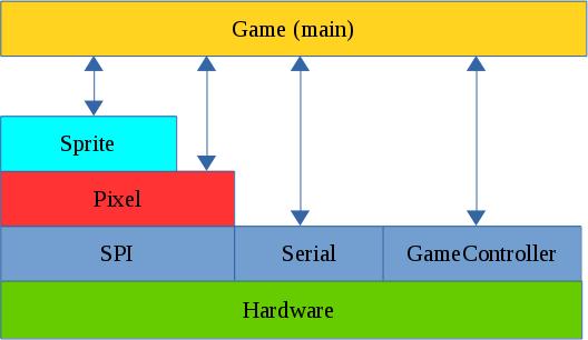
The SPI Layer
Communication with the ILI9341 display is carried out over the SPI bus. This consists of 4 signals:
MOSI (Master Out Slave In). This carries data from the LPC1114 to the ILI9341
MISO (Master In Slave Out). This carries data from the ILI9341 to the LPC1114
SCK (Serial ClocK). This is driven by the master and sets the pace for SPI Communications.
CSn or SSEL. This line is driven by the LPC1114 and can be used to wake up the ILI9341 by driving it low. The LPC1114 is capable of generating this signal automatically when transfers are taking place. This proved to be a problem in this case. The ILI9341 is slow to respond to changes to this signal and this limited data rates to less than 1 Mbit/s. This was not sufficient for the game. I noticed however that if the SSEL (CS) line is kept low all of the time the SPI bus could be run at about 24MHz. This of course means that the SPI bus is dedicated to this display which is not a problem in this case.
The Pixel Layer
This layer “understands” how to control the ILI9341. It is used to initialize the display and contains the following low level graphical functions:
putPixel
putImage
fillRectangle
putText
It also contains the macro RGBToWord which converts RGB colour values (1 byte per colour) into a 16 bit number that can be used by the ILI9341.
The Sprite Layer
typedef struct {
// Location of top left corner.
 uint16_t x;
 uint16_t y;
// Dimensions of sprite
 uint16_t width;
 uint16_t height;
// The pixels for the sprite are stored at this location
 const uint16_t *SpriteImage;
 uint8_t visible;
} Sprite;
// Construction based on 2 D pixel array
void initSprite(Sprite * sp,const uint16_t * InitArray, uint8_t Width, uint8_t Height, uint16_t x, uint16_t y);
// Show/hide the sprite
void showSprite(Sprite * sp); // Put a sprite on the display
void hideSprite(Sprite * sp); // hide the sprite
void drawSprite(Sprite * sp); // show the sprite
// Move to the specified position
void moveSprite(Sprite * sp,uint16_t x, uint16_t y); // move sprite
// Does the sprite contain the given point
uint8_t withinSprite(Sprite * sp,uint16_t x, uint16_t y);
This layer is all about Sprites : Movable pictures on the display. A sprite is defined by a data structure that specifies location, dimensions and a pointer to an array of data that contains the actual image. The remaining functions are used to show/hide and move the sprite. An additional function ‘withinSprite’ is used to test whether a given point is within the sprite. This is used to detect whether missiles or invaders have hit a target.
The game layer (main)
This layer contains all of the game logic. It also defines the shape of the various sprites used. This layer also makes calls out to the serial Communications layer allowing the developer to debug game play. Dynamic memory allocation (new/malloc etc) is not used in this project. Fixed length arrays are used for the invaders and missiles and these are enabled/disabled as necessary. One implication of this is that there can be up to 5 missiles in flight at any one time. There is still sufficient RAM available to increase this number should a developer wish to.
The video below shows the game in operation.
Code is available here on Github
MCU Invaders Part 1
Back in the 1980’s computers were a good deal simpler than they are now. This of course limited their capabilities but it also allowed people to fully understand what exactly was going on inside. Today, this is less easy as computers are extremely complex from a software and a hardware perspective. One area that still retains some of the innocence of the early days is embedded systems. Today’s low-end microcontrollers (MCU’s) are similar in specification and complexity to the home computers of the 1980’s. This makes them very attractive for re-inventing some of the classic programs of that time.
In a previous blog post I discussed a simple RPG called “MicroRealms”.
Here you will find a “Simon” lookalike.
This series of posts will describe a game inspired by Space Invaders and implemented on the LPC1114FN28 microcontroller. I will start with a description of the hardware platform and then later delve into the software and any problems encountered.
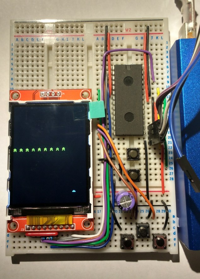
MCU Invaders hardware
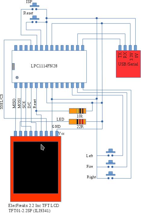
The hardware consists of an LPC1114 MCU, a 320×240 colour LCD display, some buttons, resistors and finally a USB to serial interface to allow the MCU to be programmed.
The display is driven over the SPI bus and runs at approx 25MHz (this is beyond the official specification but it seems to work fine). The buttons allow you move a defender left and right at the bottom of the screen and a “fire” button allow you launch missiles at the invader.
The MCU is programmed using ISP or IAP – i.e. programs are downloaded via its UART after it is reset into “ISP mode” (hold down Reset and ISP buttons, release Reset and then release ISP). The completed circuit is shown in the picture below.
I got the display from dx.com and I note that it is now out of stock. The original supplier ElecFreaks still has plenty of them available.
The next post will describe the code in detail bit in case you can’t wait that long you can find it over on github.