UPDATE!
3rd of March 2018
The code in this example has been updated. See here:
https://wordpress.com/post/ioprog.com/1628
In an earlier post I showed how a TLV5618 dual DAC could be interfaced to an MSP432 Launchpad. This worked OK but it was a bit slow. The code below drives the DAC’s much faster as it uses direct register writes to the SPI interface. The Energia SPI library is used to configure the interface. A single DAC channel can be driven at just over 100kHz; while a pair of channels can be updated at approx 48kHz – good enough for decent audio.
// This program drives a TLV5618 dual DAC
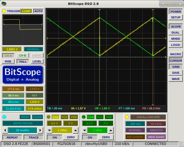
// It outputs sawtooth waveforms on both channels
// Output update frequency (both channels) is about 48kHz which
// is sufficient for decent quality audio.
// A single channel can be driven at more than 100kHz.
#include
#include
#define SS_PIN 17
void setup()
{
// put your setup code here, to run once:
pinMode(SS_PIN,OUTPUT);
pinMode(15,OUTPUT); // MOSI
pinMode(7,OUTPUT); // SCK
SPI.setModule(EUSCI_B0_MODULE); // Select correct SPI interface
SPI.setDataMode(SPI_MODE2);
SPI.setBitOrder(MSBFIRST);
SPI.setClockDivider(SPI_CLOCK_DIV2); // DIV2 = 8MHz, DIV4 = 4MHz, DIV8 = 2MHz etc. (from measurement)
UCB0CTLW0 &= ~(BIT0); // Take SPI out of reset
}
void writeDACA(int Value)
{
Value=Value & 0xfff;
Value = Value | 0xc000; // Write DAC A
digitalWrite(SS_PIN,LOW); // Drive CS low
UCB0TXBUF=( (Value >> 8) & 0xff); // write high byte
while(UCB0STATW & BIT0); // wait while SPI busy
UCB0TXBUF= ( Value & 0xff); // write low byte
while(UCB0STATW & BIT0); // wait while SPI busy
digitalWrite(SS_PIN,HIGH); // Drive CS High
}
void writeDACB(int Value)
{
Value=Value & 0xfff;
Value = Value | 0x4000; // Write DAC B value to buffer and update
digitalWrite(SS_PIN,LOW); // Drive CS low
UCB0TXBUF=( (Value >> 8) & 0xff); // write high byte
while(UCB0STATW & BIT0); // wait while SPI busy
UCB0TXBUF= ( Value & 0xff); // write low byte
while(UCB0STATW & BIT0); // wait while SPI busy
digitalWrite(SS_PIN,HIGH); // Drive CS High
}
void writeDACs(int AValue, int BValue)
{
// Write both DACs and update outputs simultaneously.
BValue=BValue & 0xfff;
BValue = BValue | 0x5000; // Write DAC B value to buffer
digitalWrite(SS_PIN,LOW); // Drive CS low
UCB0TXBUF=( (BValue >> 8) & 0xff); // write high byte
while(UCB0STATW & BIT0); // wait while SPI busy
UCB0TXBUF= ( BValue & 0xff); // write low byte
while(UCB0STATW & BIT0); // wait while SPI busy
digitalWrite(SS_PIN,HIGH); // Drive CS High
digitalWrite(SS_PIN,LOW); // Drive CS low
AValue=AValue & 0xfff;
AValue = AValue | 0xc000; // Write DAC A and update B
digitalWrite(SS_PIN,LOW); // Drive CS low
UCB0TXBUF=( (AValue >> 8) & 0xff); // write high byte
while(UCB0STATW & BIT0); // wait while SPI busy
UCB0TXBUF= ( AValue & 0xff); // write low byte
while(UCB0STATW & BIT0); // wait while SPI busy
digitalWrite(SS_PIN,HIGH); // Drive CS High
}
int i=0;
void loop()
{
// put your main code here, to run repeatedly:
while(1)
{
writeDACs(i,0xfff-i);
i++;
if (i > 0xfff)
i = 0;
}
}
The output is shown below

Thanks for your personal marvelous posting! I truly enjoyed reading
it, you are a great author. I will ensure that I bookmark your blog and
may come back later on. I want to encourage yourself to continue
your great posts, have a nice weekend!
LikeLike