The microcontroller pictured above is a curiosity. It is labelled STM32F0C8T6 and it is in an LQFP-32 package. According to ST’s datasheet, the STM32F0C8 is an LQFP-48 device so this chip should not exist. Suspecting a forgery I soldered it to a breakout board and investigated using openocd. It turns out that this is a mis-labelled STM32F0K6T6 with 4kB of RAM and 32kB of flash. Other than the faulty label it appears to be fine. Counterfit or factory reject? Who knows?
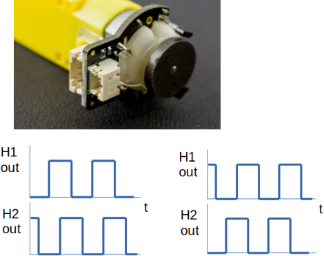
Quadrature encoders are used for measuring motor rotational speed and direction. They can be optical or magnetic just like the one below. This quadrature encoder has two Hall effect sensors which allow a program or quadrature encoder interface measure motor speed and direction.The figures above show the output from the two Hall effect sensors when the motor is running forwards and backwards. Notice how H1 has a falling edge when H2 is high on the left plot and it has a falling edge when H2 is high in the second plot. This allows a quadrature encoder interface to determine the motor direction.To measure motor speed, you need to measure pulse frequency and divide by the number of pulses produced during each cycle. The black disk in the photo above has a number of magnets embedded within it.The outputs from the Hall Effect sensors can be connected to the PhA and PhB inputs of the Tiva C on Port C (PC5,PC6).Code to initialize Quadrature Encoder Interface 1 on the Tiva C is shown below
void initQEI(void)
{

// Quadrature encoder is connected to PC5 and PC6

// These correspond to PhaseA1 and PhaseB1

SYSCTL_RCGCQEI |= (1 << 1); // enable the clock for QEI1

SYSCTL_RCGCGPIO |= (1 << 2); // enable GPIOC

SYSCTL_GPIOHBCTL |= (1 << 2); // enable AHB access to GPIOC

GPIOC_DEN |= (1 << 5) + (1 << 6); // digital mode for bits 5 and 6 of GPIOC

GPIOC_AFSEL |= (1 << 5) + (1 << 6); // alternate function mode for bits 5 and 6

GPIOC_PCTL &= ~((0x0f << 20) + (0x0f << 24)); // zero out pin control value for bits 5 and 6

GPIOC_PCTL |= ((6 << 20) + (6 << 24)); // zero out pin control value for bits 5 and 6

QEI1_CTL = 0x00000020;

QEI1_LOAD = 8000000; // This sets the timing window to 1 second when system clock is 16MHz


QEI1_MAXPOS = 1000;

QEI1_CTL |= 1;

}
The motor velocity can then be read as follows:
int getQEIVelocity()

{

int speed = QEI1_SPEED;

int direction = QEI1_STAT >> 1;

if (direction)

speed = -speed;

return speed;

}
This post was pug together on a mobile phone with a poor Internet connection. It will definitely need editing later 🙂
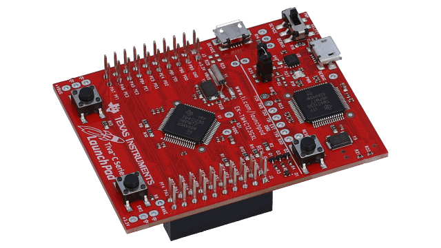
I have had reason to work with the TIVA C launchpad recently. It’s been around a while and can still be found in various retailers. I had never explored the dedicated PWM system on the device which can generate 16 outputs. Three of these are connected to the onboard RGB LEDs so you can vary brightness of them individually. The configuration is pretty straightforward as shown below:
void initPWM()
{
    SYSCTL_RCGCPWM |= (1 << 1); // turn on PWM1
    SYSCTL_RCGC2 = SYSCTL_RCGC2 | (1 << 5); // turn on GPIOF
    SYSCTL_GPIOHBCTL = SYSCTL_GPIOHBCTL | (1 << 5); // turn on AHB access to GPIOF

    // Will drive the LED's using PWM
    // PF1 -> pin 29 -> Red  -> M1PWM5 Module 1, PWM Gen 2, GPIOPCTL value = 5
    // PF2 -> pin 30 -> Blue -> M1PWM6 Module 1, PWM Gen 3, GPIOPCTL value = 5
    // PF3 -> pin 31 -> Green-> M1PWM7 Module 1, PWM Gen 3, GPIOPCTL value = 5
    GPIOF_AFSEL |= (1<<3) | (1 << 2) | (1 << 1); // select alternative function for GPIOF1,2,3
    GPIOF_DEN = GPIOF_DEN | ( (1 << 3) | (1 << 2 ) | (1 << 1) ); // digital mode bits 1,2,3 of GPIOF
    GPIOF_PCTL = (5 << 12) | (5 << 8) | (5 << 4);

    PWM1_PWMENABLE |= (1 << 7)| (1 << 6) | (1 << 5);
    PWM1_PWM2LOAD = 50000000/25000; // 25kHz assuming system clock is 50MHz
    PWM1_PWM3LOAD = 50000000/25000; // 25kHz assuming system clock is 50MHz
    // PWM counter will count down.  When it reaches 0 the output is set to zero
    // when it counts down to the value in the CMPA or CMPB register the output is
    // driven high.  This means that the duty is proportional to the value in CMPA or CMPB
    PWM1_PWM2GENB = (2 << 0) + (3 << 10); // Drive high on match, low on zero (gen b)
    PWM1_PWM3GENA = (2 << 0) + (3 << 6); // Drive high on match, low on zero (gen a)
    PWM1_PWM3GENB = (2 << 0) + (3 << 10); // Drive high on match, low on zero (gen b)
    PWM1_PWM2CMPB = 0;
    PWM1_PWM3CMPA = 0;
    PWM1_PWM3CMPB = 0;
    PWM1_PWM2CTL |= (1 << 0); // enable pwm block
    PWM1_PWM3CTL |= (1 << 0); // enable pwm block
    PWM1_PWMSYNC = 0x0f; // synchronize all counters
}
void setRed(uint32_t Percent)
{
    Percent = (Percent * PWM1_PWM2LOAD)/100;
    PWM1_PWM2CMPB = Percent;
}
void setBlue(uint32_t Percent)
{
    Percent = (Percent * PWM1_PWM3LOAD)/100;
    PWM1_PWM3CMPA = Percent;
}
void setGreen(uint32_t Percent)
{
    Percent = (Percent * PWM1_PWM3LOAD)/100;
    PWM1_PWM3CMPB = Percent;
}
The helper functions setRed,setBlue,setGreen take a single argument which represents the percentage duty. This cuts down resolution but is fine for our purposes. (The maximum possible resolution in this example is 1 in 2000 which is the reload value used by the PWM generator blocks). Full code is available over here on github. Code was developed using Code Composer Studio from Texas Instruments.
While reading an article online (https://nullprogram.com/blog/2023/04/29/) I learned that it is possible to dial up debug information levels with gcc. Previously, I would use a build command of the following form:
This worked fine but when it came to inspecting things like I/O ports defined by macros it left me with lots of work to do in a gdb debug sesssion.
Consider the following definition
typedef struct {                                /*!< (@ 0x48001400) GPIOF Structure                                            */
  __IOM uint32_t  MODER;                        /*!< (@ 0x00000000) GPIO port mode register                                    */
  __IOM uint32_t  OTYPER;                       /*!< (@ 0x00000004) GPIO port output type register                             */
  __IOM uint32_t  OSPEEDR;                      /*!< (@ 0x00000008) GPIO port output speed register                            */
  __IOM uint32_t  PUPDR;                        /*!< (@ 0x0000000C) GPIO port pull-up/pull-down register                       */
  __IM  uint32_t  IDR;                          /*!< (@ 0x00000010) GPIO port input data register                              */
  __IOM uint32_t  ODR;                          /*!< (@ 0x00000014) GPIO port output data register                             */
  __OM  uint32_t  BSRR;                         /*!< (@ 0x00000018) GPIO port bit set/reset register                           */
  __IOM uint32_t  LCKR;                         /*!< (@ 0x0000001C) GPIO port configuration lock register                      */
  __IOM uint32_t  AFRL;                         /*!< (@ 0x00000020) GPIO alternate function low register                       */
  __IOM uint32_t  AFRH;                         /*!< (@ 0x00000024) GPIO alternate function high register                      */
  __OM  uint32_t  BRR;                          /*!< (@ 0x00000028) Port bit reset register                                    */
} GPIO_Type;                                    /*!< Size = 44 (0x2c)                                                          */

#define GPIOA_BASE                  0x48000000UL
#define GPIOA                       ((GPIO_Type*)             GPIOA_BASE)
This allows me to write lines of code like this:
GPIOA->MODER |= (1 << 6); // Make bit 3 an output
In a GDB debug session it is nice to be able to look at the various registers in a port structure. Previously I would have done something like this:
print/x *((GPIO_Type *)0x48000000
This is cumbersome and requires you to know the correct names of the data structures and the various addresses they live at in memory. The blog entry mentioned above however pointed at a better way. The build command is changed as follows:
Note the “g3” i.e. turn up debugging information to the max.
Now, when I run a GDB session I can issue commands like this:
print/x *GPIOA
The extra debugging information allows GDB to work through all the macro definitions and show the contents of the port structure. Autocomplete even works :)))
This is an initial posting about early progress I have made with the BBC Microbit V2 and OpenThread. Nordic Semiconductor has posted some good example code for the NRF52840 dongle and development kit. These examples involve the Zephyr operating system and work pretty well. In particular, the echo server example is easy enough to build and deploy on an NRF52840 dongle or XIAO NRF52840 board. This can then be controlled over IPv6 as I mentioned in a previous post.
Compiling the same code for the BBC Microbit V2 initially did not work. Setting the board type to nrf52833dk_nrf52833 (the same IC that is in the Microbit) allows compilation to work but flash programming the device is difficult. I was looking for a way to do this by setting the board type to bbc_microbit_v2. The code would build, flash but not run. It seems that the configuration files for the Microbit V2 in Zephyr do not enable the 802.15.4 radio required by the Thread network. I discovered that this could be enabled by adding an app.overlay file to the project root directory with the following contents:
Compiling, flashing and running the echo_server example worked after adding this.
The next part of the journey was to add some Microbit specific I/O. I thought it would be nice to control the onboard LED matrix over the network. The echo_server code is a little complex and perhaps daunting for people starting out. I modified it a little so that a beginner could concentrate on a single C file which would handle UDP packets and I/O. This file is called usb_processor.c and is shown below:
#include <stdint.h>
#include <zephyr/logging/log.h>
#include <zephyr/kernel.h>
#include <errno.h>
#include <stdio.h>
#include <zephyr/net/socket.h>
#include <zephyr/drivers/gpio.h>
#include "matrix.h"

int initIO()
{
    int ret=0;
    ret=matrix_begin();
    return ret;
}
void udp_send_receive(uint8_t *buffer, uint32_t len)
{
    // Message is assumed to be at least 4 bytes long (a kluge for now!)
    // print the message out for debugging purposes
    if (len)
    {
        int index=0;
        while(index < len)
        {
            printk("%x ",buffer[index]);
            index++;
        }
    }
    matrix_put_pattern(buffer[0],buffer[1]);
    // pass some data back to the sender
    buffer[2]='a';
    buffer[3]='b';
}
The function initIO configures I/O devices (the LED matrix in this case – see matrix.c in the github link provided below). The function udp_send_receive is called when a UDP packet is received. In this primitive example, the first two bytes are treated as row and column bit masks for the LED matrix. The values are passed on to matrix_put_pattern. Just before returning, two characters are placed in the return packet just to verify that communications is bidirectional.
The NodeJS code that sends data to the Microbit is shown below:
var udp=require('dgram');
// -------------------- udp client ----------------

var buffer = require('buffer');

// creating a client socket
var client = udp.createSocket('udp6');

//buffer msg

client.on('message',function(msg,info){
  console.log('Data received from server : ' + msg.toString());
  console.log('Received %d bytes from %s:%d\n',msg.length, info.address, info.port);
});
//sending msg

var data = Buffer.from([0x1f,0x0,0x32,0x33]);

client.send(data,4242,'fd96:5e1e:4749:1:1fdb:ff05:1113:b755',function(error){
    if(error){
        client.close();
    } else{
        console.log('Data sent !!!');
    }
});
The IPv6 address of the Microbit has been hard-coded for now (working on network discovery next). The payload received by the Microbit is prepared in the data Buffer object. The first byte selects which rows are to be activated in the LED matrix (there are 5 of them). The second byte is selects which columns are active. In the case of columns, a ‘0’ in a particular bit activates that column.
A closing note for now: This is tricky stuff to set up and get working. I should probably put together a post that details the entire process of setting this up and running. In the meantime, if you have questions send me an email
A colleague and I are starting to experiment with silicon carbide MOSFETs. The one we have chosen to go with is from Wolfspeed. We want to drive this using an STM32G431 MCU so we opted to use an STGAP2HD isolated gate drive. This is a surface mount part so, for prototyping and evaluation purposes we build a breakout PCB
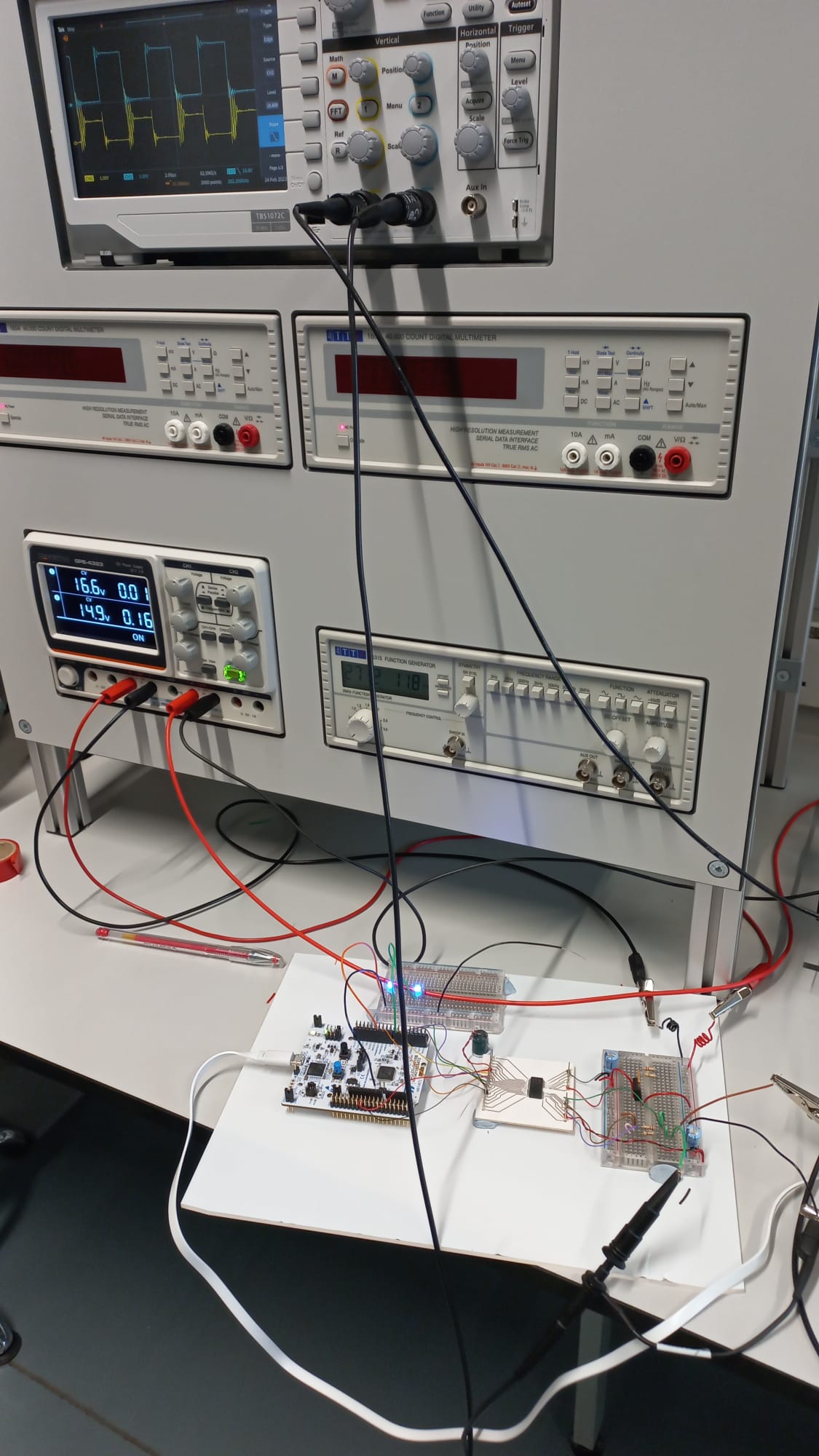
I wrote some code to generate a 130kHz PWM output signal and the driver PCB was hooked up to the power MOSFET. A long-distance shot of the system operating is show below. The blue trace on the oscilloscope is the gate drive signal while the yellow trace is the drain-source voltage. It has lots of overshoots and oscillations because of the poor layout and the inductance of the load resistor. Anyway, we are now happy that the STGAP2HD driver can actually drive our MOSFET. Next step: MUCH better layout and assemble/test one arm of an inverter bridge.
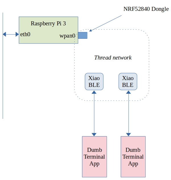
I have been experimenting with OpenThread using a RaspberryPi with Nordic 52840 Dongle and a pair of Xiao BLE modules.
The topology looks like this:
What does this let me do? As it stands I can ping either of the Xiao BLE devices from any computer on my network using IPv6. The RaspberryPi+NRF52840 dongle behave as a border router and bridges between the OpenThread/6LowPan network and the wired Ethernet.
This has not been entirely straightforward so far. The XIAO-BLE devices are running Zephyr’s sample echo_server built with this command line:
west build -b xiao_ble echo_server -- -DCONF_FILE="prj.conf overlay-ot.conf"
Prior to this, the project configuration file (prj.conf) was modified as follows:
# Generic networking options
CONFIG_NETWORKING=y
CONFIG_NET_UDP=y
CONFIG_NET_TCP=y
CONFIG_NET_IPV6=y
CONFIG_NET_IPV4=y
CONFIG_NET_SOCKETS=y
CONFIG_NET_SOCKETS_POSIX_NAMES=y
CONFIG_POSIX_MAX_FDS=6
CONFIG_NET_CONNECTION_MANAGER=y

# Kernel options
CONFIG_MAIN_STACK_SIZE=2048
CONFIG_ENTROPY_GENERATOR=y
CONFIG_TEST_RANDOM_GENERATOR=y
CONFIG_INIT_STACKS=y

# Logging
CONFIG_NET_LOG=y
CONFIG_LOG=y
CONFIG_NET_STATISTICS=y
CONFIG_PRINTK=y

# Network buffers
CONFIG_NET_PKT_RX_COUNT=16
CONFIG_NET_PKT_TX_COUNT=16
CONFIG_NET_BUF_RX_COUNT=64
CONFIG_NET_BUF_TX_COUNT=64
CONFIG_NET_CONTEXT_NET_PKT_POOL=y

# IP address options
CONFIG_NET_IF_UNICAST_IPV6_ADDR_COUNT=3
CONFIG_NET_IF_MCAST_IPV6_ADDR_COUNT=4
CONFIG_NET_MAX_CONTEXTS=10

# Network shell
CONFIG_NET_SHELL=y
CONFIG_SHELL=y

# Network application options and configuration
CONFIG_NET_CONFIG_SETTINGS=y
CONFIG_NET_CONFIG_NEED_IPV6=y
#CONFIG_NET_CONFIG_MY_IPV6_ADDR="2001:db8::3"
#CONFIG_NET_CONFIG_PEER_IPV6_ADDR="2001:db8::1"
#CONFIG_NET_CONFIG_NEED_IPV4=y
#CONFIG_NET_CONFIG_MY_IPV4_ADDR="192.0.2.1"
#CONFIG_NET_CONFIG_PEER_IPV4_ADDR="192.0.2.2"

# Number of socket descriptors might need adjusting
# if there are more than 1 handlers defined.
CONFIG_POSIX_MAX_FDS=12

# How many client can connect to echo-server simultaneously
CONFIG_NET_SAMPLE_NUM_HANDLERS=1

CONFIG_OPENTHREAD_DHCP6_SERVER=y
CONFIG_OPENTHREAD_SLAAC=y
CONFIG_NET_IF_UNICAST_IPV6_ADDR_COUNT=6
# need to add this so that the module can join the thread network
CONFIG_OPENTHREAD_JOINER=y
This creates a file called Zephyr.uf2 which is copied to the XIAO devices when they are in UF2 bootloader mode (press the button on them twice).
(The NRF52840 dongle has to be in DFU mode for the last line to work)
Finally, the raspberry pi 3 had to be set up. This is running Raspbian and the OpenThread border router services were obtained by cloning https://github.com/openthread/ot-br-posix, building and compiling (and much fiddling about!).
Where to from here? Well, the whole point of this experiment is to compare the BLE/GATT/GAP approach to IoT to one using IPv6 and “traditional” network function calls.
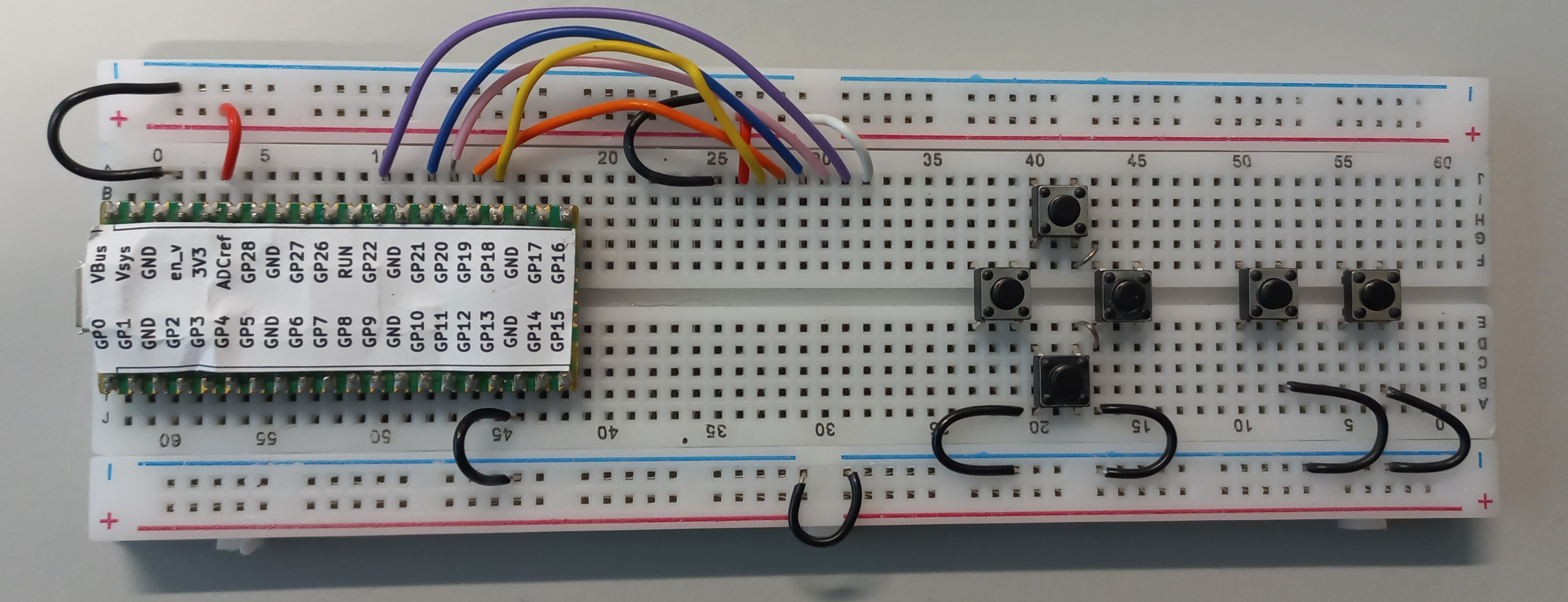
There are two sets of co-ordinates shown on the board. We will be using the ones that are the “right way up” i.e. the ones shown on the left side of the image. Some of the images can be a little misleading because of the angle the photos were taken. This is particularly true for the red and black wires at the top left of the image. The red wire connects to 3V3 to any hole just above the red line. The black wire connects GND to any hole just below the blue wire.
Display wiring:
White : Column 32, Row A to any hole just above the red line (keep it left of Column 30)
Purple : Column 31, Row A to GP22
Pink : Column 30, Row A to GP20
Blue : Column 29, Row A to GP21
Orange : Column 28, Row A to GP19
Yellow : Column 27, Row A to GP18
Red : Column 26, Row A to any hole just above the red line (3.3V)
Black : Column 25, Row A to any hole just below the blue line (0V)
Buttons: Place as shown.
Black wires (0V) These are used connect GND (0V) signals together.
Link wires between buttons
Column 42, Row E to Column 43, Row D
Column 42, Row F to Column 43, Row G
Button wiring. Try to get at least some of the button wires into the channel between the top and bottom halves of the breadboard.
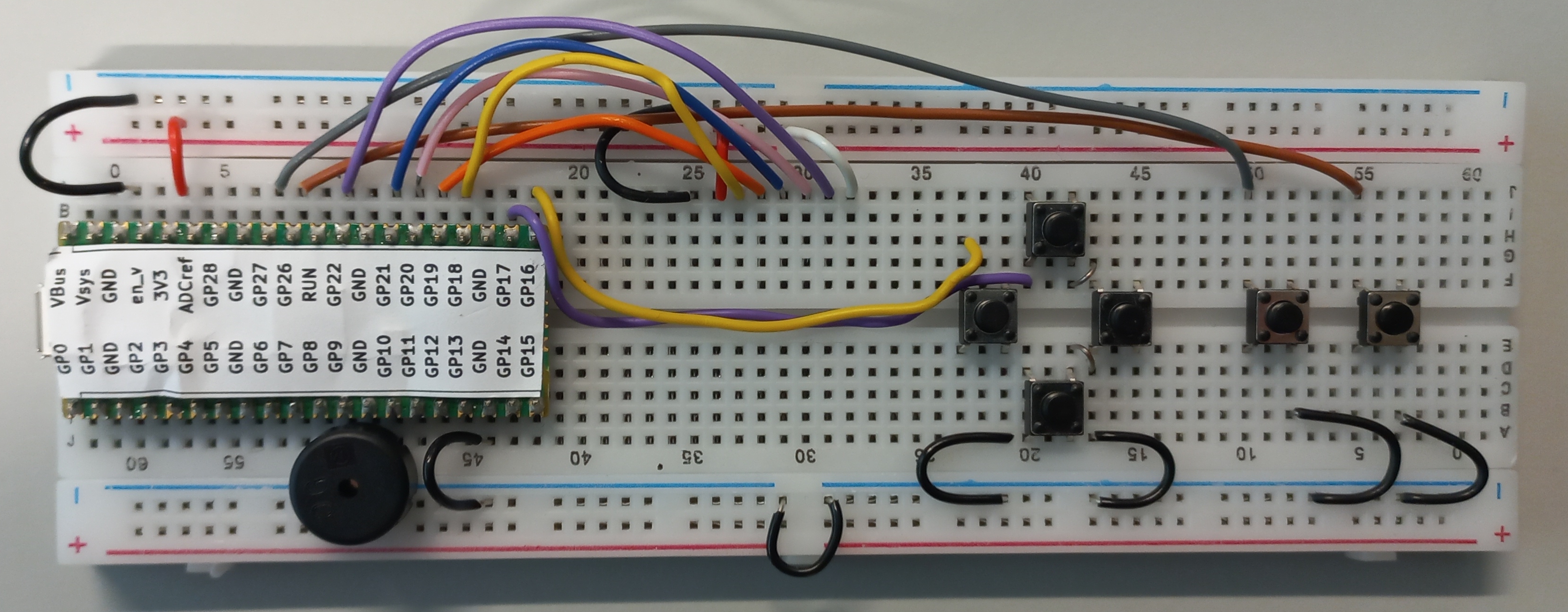
Brown : GP26 to Column 55, Row A
Grey : GP27 to Column 50, Row A
Purple : GP17 to Column 14, Row E
Buzzer: GP9 to any hole just below the blue line
Yellow: GP16 to Column 36, Row C
White : GP15 to Column 45, Row C
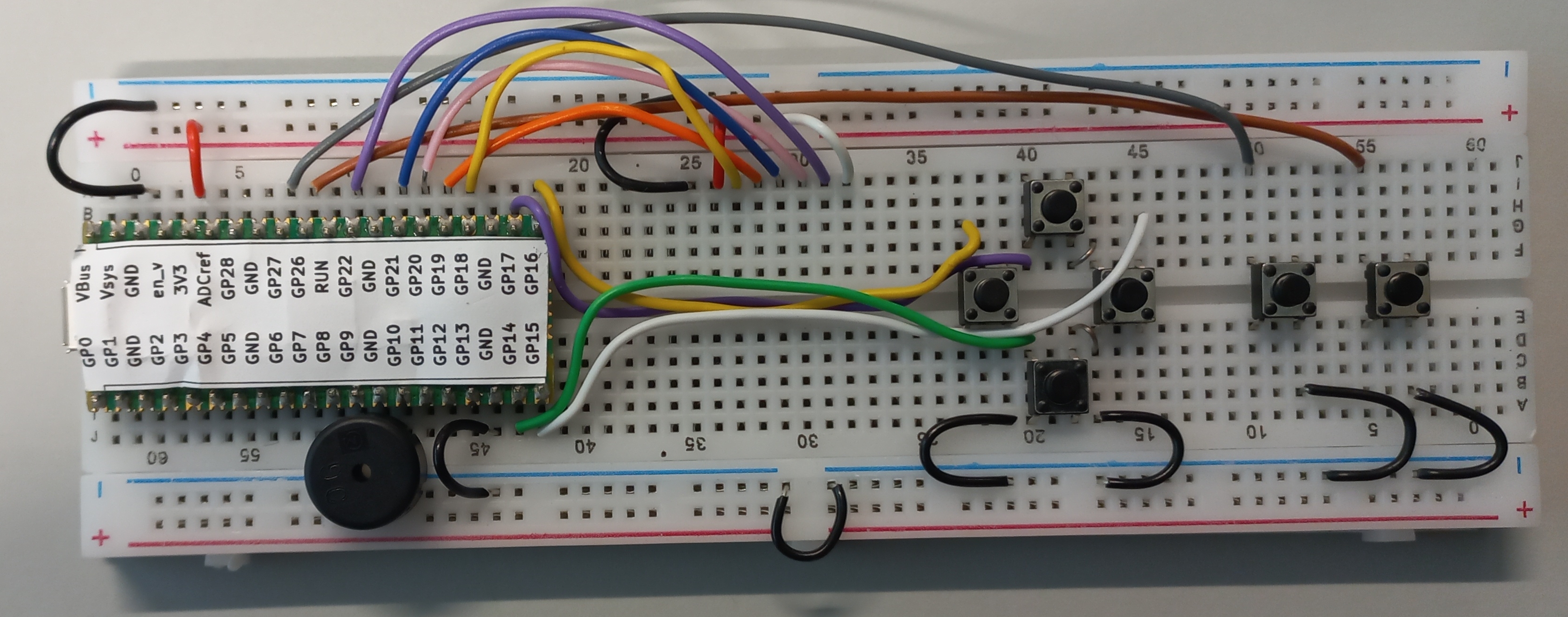
Green: GP14 to Column 40, Row F
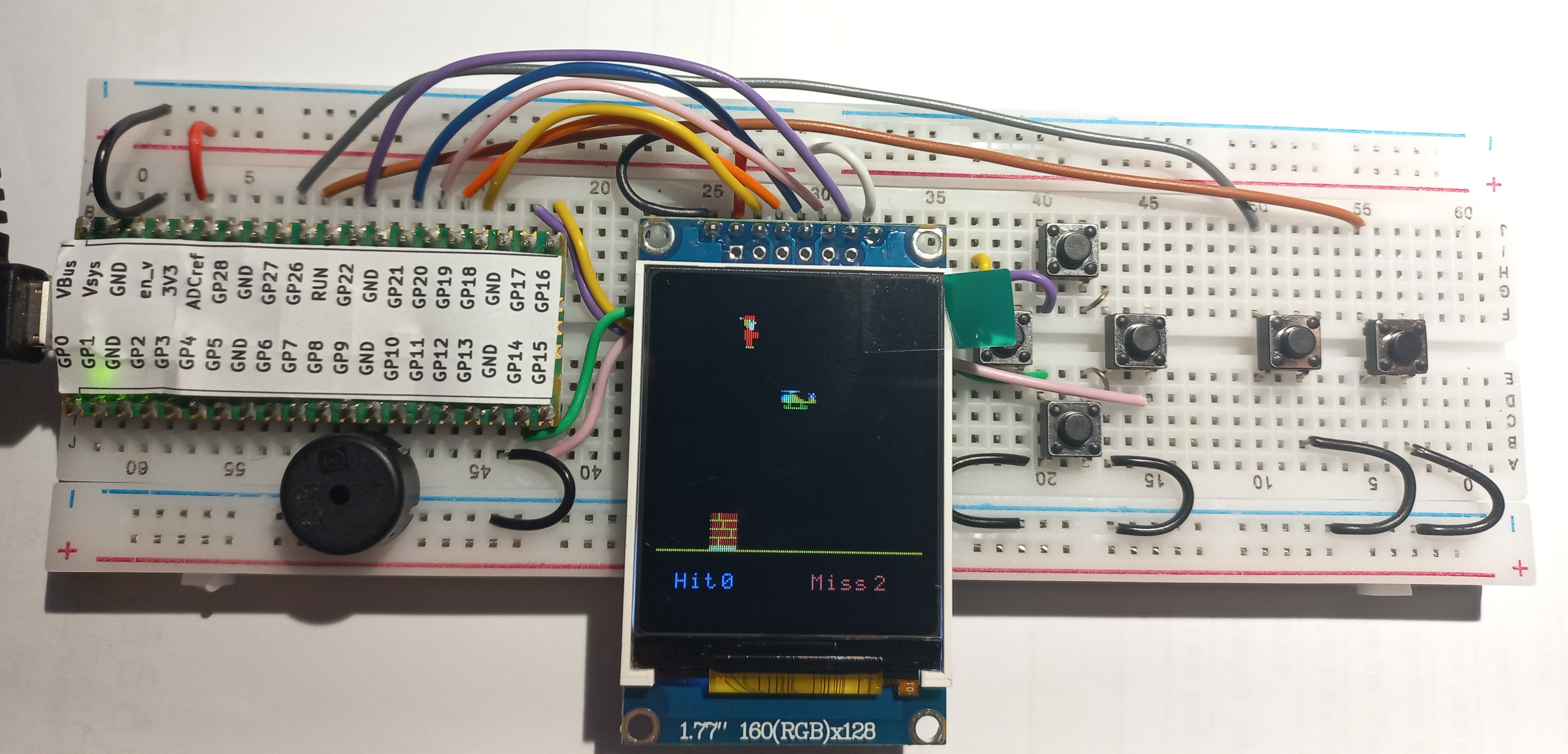
WARNING : ASK FOR ASSISTANCE WITH THIS. DISPLAY ARE FRAGILE!
Fit the display as shown in the row of holes just below the display wires. The rightmost pin of the display should line up with the small white wire.
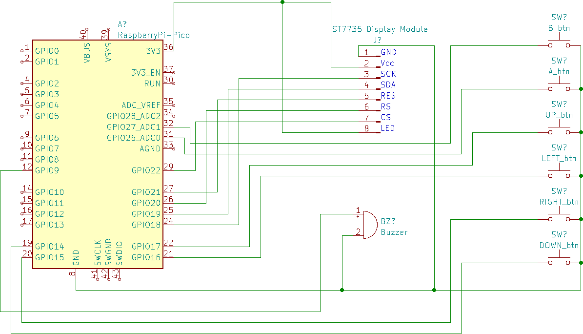
Breadboard Games 2022 is approaching. This year we will have 16 students assemble the game console shown above. The console consists of a Raspberry Pi Pico linked to an ST7735, some buttons and a piezo speaker. The schematic is shown below
Two simple games are featured: A version of break out and a simple Santa Clause game. These games are written in Micropython with an emphasis on ease of understanding rather than game play. Nevertheless, the graphics module is reasonably optimized with an inline assembler module that executes very quickly and which is used by API functions as much as possible. Furthermore, the sound module makes use of the second core in the Pico which allows sound to be be played at the same time as the game.
The game sprites are edited in a bitmap editor such as Windows Paint or KolourPaint etc. The sprites are created as 24 bit bitmap (bmp) files. A python script converts these bitmaps to python arrays on the host computer. These arrays are coded as 16 bit RGB (5-6-5) colour values which are compatible with the ST7735. These arrays are then included in a sprite module in the game.
Programs were edited using Thonny which is a nice cross-platform editor that works with a number of operating systems. It can be installed without administrator permissions on Windows and Linux systems.
I have been working on a graphics library for the ST7735 and the Raspberry Ri Rico. The first version was written in pure micropython and worked well enough but was quite slow – especially when writing out blocks of colour (fillRectangle). This was the original code for fillRectangle:
It makes use of an inline assembler function the source code of which is as follows:
@micropython.asm_thumb
    def fill_block(r0,r1,r2):
        # pointer to self passed in r0
        # r1 contains the 16 bit data to be written
        # r2 countains count
        # Going to use SPI0.
        # Base address = 0x4003c000
        # SSPCR0 Register OFFSET 0
        # SSPCR1 Register OFFSET 4
        # SSPDR Register OFFSET 8
        # SSPSR Register OFFSET c
        push({r1,r2,r3,r4,r7})
        # Convoluted load of a 32 value into r7
        mov(r7,0x40)
        lsl(r7,r7,8)
        add(r7,0x03)
        lsl(r7,r7,8)
        add(r7,0xc0)
        lsl(r7,r7,8)
        add(r7,0x00)
        mov(r4,2)
        label(fill_block_loop_start)
        cmp(r2,0)
        beq(fill_block_exit)
        mov(r3,r1) # read next byte
        lsr(r3,r3,8)
        strb(r3,[r7,8]) # write to SPI
        label(fill_block_spi_wait1)
        ldr(r3,[r7,0xc]) # read next byte
        and_(r3,r4)
        beq(fill_block_spi_wait1)

        mov(r3,r1) # read next byte
        strb(r3,[r7,8]) # write to SPI
        sub(r2,r2,1) # decrement count
        label(fill_block_spi_wait2)
        ldr(r3,[r7,0xc]) # read next byte
        and_(r3,r4)
        beq(fill_block_spi_wait2)
        b(fill_block_loop_start)

        label(fill_block_exit)
        pop ({r1,r2,r3,r4,r7})
This writes the colour value directly to the SPI port the required number of times. It needs to pause when the SPI FIFO fills up (hence he need for the labels fill_block_spi_wait1/2).
The performance improvement is about a factor of 20!
Code is available over on gihub and is likely to change lots in the next couple of weeks while I prepare for a STEM event.