Serial communications using the STM32F042 Nucleo board

A previous post demonstrated semihosting which should be used to communicate with a host PC during unexpected fault conditions. For more general communications you can use the built-in serial port in the STLink-V2 interface. This is connected to USART2 in the STM32F042.
This simple program blinks the on-board LED and sends an ever increasing count (in HEX) to the host PC


/* 
 * Blinky: Switch the MCU to highest speed and blink the LED attached 
 * to port B, bit 3
*/


#include "stm32f042.h"

void delay(int);

void delay(int dly)
{
  while( dly--);
}

void initClock()
{
// This is potentially a dangerous function as it could
// result in a system with an invalid clock signal - result: a stuck system
        // Set the PLL up
        // First ensure PLL is disabled
        RCC_CR &= ~BIT24;
        while( (RCC_CR & BIT25)); // wait for PLL ready to be cleared
        // set PLL multiplier to 12 (yielding 48MHz)
  // Warning here: if system clock is greater than 24MHz then wait-state(s) need to be
        // inserted into Flash memory interface
        FLASH_ACR |= BIT0;
        FLASH_ACR &=~(BIT2 | BIT1);

        // Turn on FLASH prefetch buffer
        FLASH_ACR |= BIT4;
        RCC_CFGR &= ~(BIT21 | BIT20 | BIT19 | BIT18);
        RCC_CFGR |= (BIT21 | BIT19 ); 

        // Need to limit ADC clock to below 14MHz so will change ADC prescaler to 4
        RCC_CFGR |= BIT14;

// Do the following to push HSI clock out on PA8 (MCO)
// for measurement purposes.  Should be 8MHz or thereabouts (verified with oscilloscope)
/*
        RCC_CFGR |= ( BIT26 | BIT24 );
        RCC_AHBENR |= BIT17;
        GPIOA_MODER |= BIT17;
*/

        // and turn the PLL back on again
        RCC_CR |= BIT24;        
        // set PLL as system clock source 
        RCC_CFGR |= BIT1;
}

void configPins()
{
	// Power up PORTB
	RCC_AHBENR |= BIT18;
	
}	

int main()
{
	unsigned count=0;
	initClock();
	initUART(9600);
	unsigned i=0;
	configPins(); 
	GPIOB_MODER |= BIT6; // make bit3  an output
	GPIOB_MODER &= ~BIT7; // make bit3  an output
	while(1)
	{
		printHex(count++);
		GPIOB_ODR |= BIT3;
		delay(200000);
		eputs("\r\n");
		GPIOB_ODR &= ~BIT3;
		delay(200000);
		
	} 
	return 0;
}

Full code is available here:
http://eleceng.dit.ie/frank/arm/BareMetalSTM32F042Nucleo/index.html

Semihosting on the STM32F042 Nucleo board

The STM32F042 Nucleo board is a nice, low cost development board that is suitable for breadboard based development.  It includes an STLink-V2 debug interface which allows semihosting when used in conjunction with OpenOCD.
Semihosting allows a program send debug messages back to a host during development. It is of little use as a general communications interface as the processor simply stops running if the host is not attached (and running openocd or equivalent). Its main use however is to help you diagnose tricky faults during development. I decided to use it to trap unhandled interrupts which were generated by writing to a bad memory address as shown below:

unsigned *BadMemoryAddress;
:
:
// Point at a known bad memory address (reserved/unconnected space)
	BadMemoryAddress = (unsigned *)0xfffffffc;
:
// Generate a hard fault (exception number 3)
// by writing to a bad memory address
	*BadMemoryAddress = 42;

For my implementation, the Hard Fault interrupt vector simply pointed to a default handler which is shown here:

void Default_Handler(void)
{
// Reference: http://infocenter.arm.com/help/index.jsp?topic=/com.arm.doc.dui0552a/Babefdjc.html 
// Note: Using a different compiler or changing compiler options may change the stack ordering
/* Stack on entry:
 * 	xPSR				offset 44
 * 	PC					offset 40
 *	LR					offset 36
 * 	R12					offset 32
 * 	R3					offset 28
 * 	R2					offset 24
 * 	R1					offset 20
 * 	R0					offset 16
 * 	FramePointer		offset 12
 * 	LR					offset 8
 * 	local variable 1	offset 4
 * 	local variable 2	offset 0
 * 
 */
	unsigned status;
	unsigned stackpointer;
	// Read the contents of the IPSR register 
	// This should contain the exception number
	asm("mrs %[status], ipsr \r\n"
	 : [status]"=rm"(status)
	 :
	 :
	 );
	asm("mov %[stackpointer],sp \r\n"
	 : [stackpointer]"=rm"(stackpointer)
	 :
	 :
	 );
	debug_printString("\r\nUnhandled exception.\r\nIPSR =  ");
	debug_printInteger(status);
	debug_printString("\r\nLast instruction location = ");	
	debug_printInteger(*(unsigned *)(stackpointer+40));
	// while(1);  Uncomment this if you want to processor to stop here.
	
}

This code outputs the Interrupt Program Status Register (IPSR) contents to openocd (you will see it in the console where openocd was invoked) as well as the value of the Program Counter when the exception/interrupt occurred. The IPSR register contains the exception number which should be 3 for a hard fault like this.
The debug_printString and debug_PrintInteger functions are provided in the source code which is available at
http://eleceng.dit.ie/frank/arm/BareMetalSTM32F042Nucleo/index.html

STM32Nucleo driving a H-bridge

A previous blog post listed Mbed code for generating sinusoidal PWM using an STM32F103 Nucleo board.  A simple H-bridge was connected to the Nucleo board and used to drive a loud speaker.  The circuit happily delivered more than 5W to a load during testing and would have delivered more had I found a suitable power supply.  The H-bridge circuit makes use of IRS2003 gate drivers as shown below.

circuit

The current (red) and voltage (yellow) waveforms produced by the H-Bridge are shown below

ScopeVI

The video clip below allows you hear the 50Hz and 10kHz harmonics produced by the circuit.

Sinusoidal PWM on the STM32F103 Nucleo board

This example was developed in the mbed online compiler. It makes some use of the mbed libraries but goes beyond them to manage interrupts and complimentary PWM outputs.
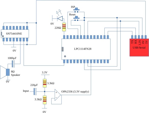
The switching frequency is 10kHz and the modulating frequency is 50Hz. This example was used to drive a H-bridge with a speaker connected as load. The interesting part of this is that you can hear the 10kHz quite clearly and the 50Hz component amplitude rises and falls as you adjust the potentiometer. The numbers for the sinusoidal duty cycles were calculated by Richard Hayes using octave.
The code makes use of some of STM32 Standard Peripheral Library and avoids the HAL libraries (I’ve had limited success here).

// This program outputs a 50Hz complimentary Sinusoidal PWM signal on PA8 and PB13.
// The switching speed is 10kHz.  The program uses a mix of mbed functions and
// direct register writes.  It makes use of a lookup table generated in Octave (Thanks Richard Hayes)
// and interrupts to update the duty cycle.
// A potentiometer is attached to A0 and this can be used to control the amplitude modulation index.
// Useful reference: http://stm32.kosyak.info/doc/index.html
#include "mbed.h"
// Define some bitmasks
#define BIT0 (1 << 0)
#define BIT1 (1 << 1)
#define BIT2 (1 << 2)
#define BIT3 (1 << 3)
#define BIT4 (1 << 4)
#define BIT5 (1 << 5)
#define BIT6 (1 << 6)
#define BIT7 (1 << 7)
#define BIT8 (1 << 8)
#define BIT9 (1 << 9)
#define BIT10 (1 << 10)
#define BIT11 (1 << 11)
#define BIT12 (1 << 12)
#define BIT13 (1 << 13)
#define BIT14 (1 << 14)
#define BIT15 (1 << 15)
#define BIT16 (1 << 16)
#define BIT17 (1 << 17)
#define BIT18 (1 << 18)
#define BIT19 (1 << 19)
#define BIT20 (1 << 20)
#define BIT21 (1 << 21)
#define BIT22 (1 << 22)
#define BIT23 (1 << 23)
#define BIT24 (1 << 24)
#define BIT25 (1 << 25)
#define BIT26 (1 << 26)
#define BIT27 (1 << 27)
#define BIT28 (1 << 28)
#define BIT29 (1 << 29)
#define BIT30 (1 << 30)
#define BIT31 (1 << 31)
DigitalOut myled(LED1);
const int duties[]={\
    50,51,53,54,56,57,59,60,62,63,65,66,68,69,71,72,74, \
    75,76,78,79,80,81,83,84,85,86,87,88,89,90,91,92,93,\
    93,94,95,95,96,97,97,98,98,98,99,99,99,99,99,99,100,\
    99,99,99,99,99,99,98,98,98,97,97,96,95,95,94,93,93,\
    92,91,90,89,88,87,86,85,84,83,81,80,79,78,76,75,74,\
    72,71,69,68,66,65,63,62,60,59,57,56,54,53,51,49,48,\
    46,45,43,42,40,39,37,36,34,33,31,30,28,27,25,24,23,\
    21,20,19,18,16,15,14,13,12,11,10,9,8,7,6,6,5,4,4,3,\
    2,2,1,1,1,0,0,0,0,0,0,0,0,0,0,0,0,0,1,1,1,2,2,3,4,4,\
    5,6,6,7,8,9,10,11,12,13,14,15,16,18,19,20,21,23,24,\
    25,27,28,30,31,33,34,36,37,39,40,42,43,45,46,48\    
};
/*
Pin mappings for Timer 1 (the advanced timer with deadtime)
From: https://developer.mbed.org/users/mbed_official/code/mbed-src/file/a11c0372f0ba/targets/hal/TARGET_STM/TARGET_STM32F1/TARGET_NUCLEO_F103RB/PeripheralPins.c
    {PA_8,  PWM_1, STM_PIN_DATA(STM_MODE_AF_PP, GPIO_PULLUP, 0)}, // TIM1_CH1 - Default
    {PA_9,  PWM_1, STM_PIN_DATA(STM_MODE_AF_PP, GPIO_PULLUP, 0)}, // TIM1_CH2 - Default
    {PA_10, PWM_1, STM_PIN_DATA(STM_MODE_AF_PP, GPIO_PULLUP, 0)}, // TIM1_CH3 - Default
    {PB_13, PWM_1, STM_PIN_DATA(STM_MODE_AF_PP, GPIO_PULLUP, 0)}, // TIM1_CH1N - Default
    {PB_14, PWM_1, STM_PIN_DATA(STM_MODE_AF_PP, GPIO_PULLUP, 0)}, // TIM1_CH2N - Default
    {PB_15, PWM_1, STM_PIN_DATA(STM_MODE_AF_PP, GPIO_PULLUP, 0)}, // TIM1_CH3N - Default
 
*/
// Use mbed to configure the relevant pins as PWM outputs;
PwmOut      PhaATop(PA_8);    
PwmOut      PhaABtm(PB_13);  // This should be the complement of PA_8  
AnalogIn    Pot(A0);
volatile float PotValue;
void init(void);
int main() {    

    init();
    while(1) {
        myled = 1; // LED is ON
        wait(0.1); // 200 ms
        myled = 0; // LED is OFF
        wait(0.1); // 1 sec        
        PotValue = Pot;
    }
}

int ScaleDuty(int Duty,float factor)
{
    float ScaledDuty = Duty;
    ScaledDuty = (ScaledDuty - 50) * factor;
    ScaledDuty = ScaledDuty + 50;
    return ScaledDuty;
}
int index=0;
void TimerISR()
{       
    TIM1->SR &= ~0x3f; // ack the interrupt    
    TIM1->CCR1=ScaleDuty(duties[index++],PotValue); // get the next duty
    if (index > 199)
        index = 0;   
}
void init()
{
    
    RCC->APB2ENR |= BIT2+BIT3;  // enable GPIOA and GPIOB    
    RCC->APB2ENR |= BIT11;      // enable TIM1
    
    GPIOA->CRH |= BIT3+BIT0;    // PA8 output, alternate function
    GPIOB->CRH |= BIT23+BIT20;  // PB13 output, alternate function
    
    TIM1->CR2 = 0;
    TIM1->DIER = BIT0; // Want update interrupt
    NVIC_SetVector(TIM1_UP_IRQn,(uint32_t) TimerISR);   
    NVIC_EnableIRQ(TIM1_UP_IRQn);
    TIM1->SR = 0;      // Clear flags.
    TIM1->CCMR1= BIT6+BIT5+BIT4;
    TIM1->CCER = BIT2+BIT0;
    TIM1->ARR = 100;  // 1MHz = base clock freq.  Divide by 100 to get 10kHz.
    TIM1->CCR1 = 10;  // Low inital duty
    TIM1->CR1 |= BIT0; //enable counter
     __enable_irq();   // enable interrupts

}

Energia MSP430G2553 Timer interrupts Version 2

Previously I had developed a simple demonstrator of timer interrupts on the MSP430 Launchpad with Energia. This sort of worked but I failed to acknowledge the interrupt in the timer control register so the foreground function (loop) never ran. This version fixes that and tidies up the code a little. In this program the foreground function toggles the red LED and the interrupt service routine toggle the green LED.

#include <msp430.h>
void setup()
{
  // put your setup code here, to run once:
  pinMode(P1_6,OUTPUT); // make the LED pin outpu  
  pinMode(P1_0,OUTPUT);
  setupTimer(1000); // set timer period to 1000 micro seconds  
}

void loop()
{
  digitalWrite(P1_0,HIGH);
  delay(100);
  digitalWrite(P1_0,LOW);
  delay(100);
  
}
void OnTimer()
{
  static int msCount=0;// Count milliseconds to allow a 1 second pulse
  static int state=0;  // Remember LED state for toggling purposes

  msCount++;
  if (msCount >= 1000)
  {
    msCount = 0;
    digitalWrite(P1_6,state); // Write to LED
    state=~state;             // toggle state
  }

}
void setupTimer(unsigned Period)
{
  // Configuration word
  // Bits 15-10: Unused
  // Bits 9-8: Clock source select: set to SMCLK (16MHz)
  // Bits 7-6: Input divider: set to 8
  // Bits 5-4: Mode control: Count up to TACCRO and reset
  // Bit 3: Unused
  // Bits 2: TACLR : set to initially clear timer system
  // Bit 1: Enable interrupts from TA0
  // Bit 0: Interrupt (pending) flag : set to zero (initially)
  TA0CTL=0b0000001011010010; 
  TACCR0=Period*2; // Set TACCR0 = Period*2 (2MHz clock)
  TACCTL0=BIT4; // Enable interrupts when TAR = TACCR0  
}
// The address function that follows this vector statement is placed in the specified location Interrupt Vector table 
#pragma vector=TIMER0_A0_VECTOR
__interrupt  void timerA0ISR(void)
{
// Timer A0 Interrupt service routine
  OnTimer();
  TA0CTL &= ~BIT0;     // Acknowledge the interrupt
      
}

MBed, STM32Nucleo and complimentary outputs.

After a few days of trying to get the complimentary outputs on the STM32F103 Nucleo going I’ve finally succeeded. It was surprisingly simple in the end but there is a general lack of documentation and I wonder at the completeness of the PWM API. Anyway, here is a platform specific working example. It produces a two channels of complimentary output signals (i.e. 4 outputs in total) running at 1kHz with 80% duty and an deadtime of about 13.5uS.

#include "mbed.h"
DigitalOut  my_led(LED1);

/*
Pin mappings for Timer 1 (the advanced timer with deadtime)
From: https://developer.mbed.org/users/mbed_official/code/mbed-src/file/a11c0372f0ba/targets/hal/TARGET_STM/TARGET_STM32F1/TARGET_NUCLEO_F103RB/PeripheralPins.c
    {PA_8,  PWM_1, STM_PIN_DATA(STM_MODE_AF_PP, GPIO_PULLUP, 0)}, // TIM1_CH1 - Default
    {PA_9,  PWM_1, STM_PIN_DATA(STM_MODE_AF_PP, GPIO_PULLUP, 0)}, // TIM1_CH2 - Default
    {PA_10, PWM_1, STM_PIN_DATA(STM_MODE_AF_PP, GPIO_PULLUP, 0)}, // TIM1_CH3 - Default
    {PB_13, PWM_1, STM_PIN_DATA(STM_MODE_AF_PP, GPIO_PULLUP, 0)}, // TIM1_CH1N - Default
    {PB_14, PWM_1, STM_PIN_DATA(STM_MODE_AF_PP, GPIO_PULLUP, 0)}, // TIM1_CH2N - Default
    {PB_15, PWM_1, STM_PIN_DATA(STM_MODE_AF_PP, GPIO_PULLUP, 0)}, // TIM1_CH3N - Default
 
*/

int main()
{

    PwmOut      PhaATop(PA_8);    
    PwmOut      PhaABtm(PB_13);  // This should be the complement of PA_8    
    PwmOut      PhaBTop(PA_9);    
    PwmOut      PhaBBtm(PB_14);  // This should be the complement of PA_9   
    PhaATop.period_ms(1);
    PhaATop = 0.8;       
    PhaBTop.period_ms(1);
    PhaBTop = 0.8;             
    TIM1->CCER |= 4; //enable ch1 complimentary output
    TIM1->BDTR |= 0xff; // specify the maximum amount of deadtime required approx 13.5us - see page 356 of reference manual
    TIM1->CCER |= 64; //enable ch2 complimentary output
    TIM1->BDTR |= 0xff; // specify the maximum amount of deadtime required approx 13.5us - see page 356 of reference manual
    while (1) {
        my_led = !my_led;
        wait(0.2); // 500 ms
    }
}

Minimal blinky in ARM Cortex M0 assembler

Update: A variation of this for the LPC11148FN28 can be found here
I wanted to try to write a minimal assembler blinky program that flashes the blue LED on an STM32F0 Value Line discovery board (STM32F030R8T6 MCU).
The linker script and Makefile are tagged on at the end

// Minimal assembler blinky example for stm32f030 
// (stm32f0 Value line discovery board)
// LED is on GPIOC bit 8

		.thumb  	// Cortex micros only understand thumb(2) code	
		.syntax unified // use newer style instructions
			
		.text		// what follows is code
// Set up interrupt vector table: 
// entry 0: initial stack pointer
// entry 1: reset address
Vector_Table:    
		.word     0x20002000          // Top of Stack 
/* The interrupt vectors that follow are manually forced 
   to be aligned along odd addresses.  The reason for this
   is that the address for a Thumb instruction must always 
   have its LSB set to 1.  This does not mean that the 
   instruction is stored at an odd number address.  The 
   LSB is used as a flag to indicate that an ARM (LSB=0) 
   or a Thumb (LSB=1) instruction is being addressed. 
*/
ResetVector:    .word     start + 1     // Reset Handler 

// the program starts here 
start:
// Do initial IO configuration
// Turn on clock for GPIOC		
		ldr R1,=RCCAHBENR		// pointer to register 
		ldr R2,=RCCAHBENRMASK	// mask
		bl	set_bits
// Make port pin behave as an output
		ldr R1,=GPIOCMODER		// pointer to register 
		ldr R2,=GPIOCMODERMASK	// mask
		bl	set_bits
		
// Now enter the main loop
main_loop:
// Turn LED on
		ldr R1,=GPIOCODR	// pointer to register 
		ldr R2,=LEDMASK		// mask
		bl 	set_bits
// wait a while
		ldr R0,=DELAYLENGTH		
		bl delay

// Turn LED off
		ldr R1,=GPIOCODR	// pointer to register 
		ldr R2,=LEDMASK		// mask
		bl	clear_bits

// wait a while
		ldr R0,=DELAYLENGTH
		bl delay

		b	main_loop		// branch back to start of loop 
		
// subroutines are down here		
// Delay subroutine.  Pass the length of the delay in R0
delay:	subs R0,R0,#1
		bne delay
		bx LR

// on entry, R1 contains address where target address is stored
// R2 contains address where mask bits are stored
set_bits: 
		ldr R0,[R1]			// read register contents
		orrs R0,R0,R2		// combine with register contents
		str R0,[R1]			// write back contents
		bx LR				// return to caller
// on entry, R1 contains address where target address is stored
// R2 contains address where mask bits are stored
clear_bits: 
		ldr R0,[R1]			// read register contents
		bics R0,R0,R2		// combine with register contents
		str R0,[R1]			// write back contents
		bx LR				// return to caller
		
	
// constant definitions are below here.

		.equ RCCAHBENR,	0x40021014
		.equ GPIOCMODER, 0x48000800
		.equ GPIOCODR,	0x48000814


		.equ RCCAHBENRMASK,	0x00080000
		.equ GPIOCMODERMASK, 0x00010000
		.equ LEDMASK, 0x00000100
		.equ DELAYLENGTH, 0x000fffff


Linker script

MEMORY
{
    flash : org = 0x08000000, len = 64k
    ram : org = 0x20000000, len = 8k
}
  
SECTIONS
{
        
	. = ORIGIN(flash);
        .text : {
		
        } &amp;gt;flash
	. = ORIGIN(ram);
        .data : {
              		
        } &amp;gt;ram
}

Makefile

# Specify the assembler to use
AS=arm-none-eabi-as
# Specity the linker to use
LD=arm-none-eabi-ld

ASFLAGS=-mcpu=cortex-m0 -mthumb -g 
# List the object files involved in this project
OBJS=	blinky.o 
blinky.elf : $(OBJS)
	$(LD) $(OBJS) -T linker_script.ld --cref -Map blinky.map -nostartfiles -o main.elf
	 objcopy -O ihex main.elf main.hex
blinky.o: blinky.s
	$(AS) $(ASFLAGS) blinky.s -asghl=blinky.lst -o blinky.o
# if someone types in 'make clean' then remove all object files and executables
# associated wit this project
clean: 
	rm $(OBJS) 
	rm blinky.elf 

Low power sensor node follow up to follow up

The STM32F030/NRF24L01+ low power sensor node has been running since August 14 on a pair of cheap generic AA batteries. The node transmits data (brightness) every second and will retry up to 15 times if it fails to get an ACK from the base station. For most of this time the base station has been off so those retries have been happening. Energy consumption has been much higher than it should have been nevertheless the device is still running.