Low pass filtering using the STML432 Nucleo

This example uses a 4th order Butterworth low pass filter that was designed in GNU Octave.  The sampling rate was set to 200kHz and the cut-off frequency was set to 20kHz.  The filter output at 20kHz is shown below and, as expected, shows an attenuation of 0.7 (approx the square root of 2).

FilterOutput1

Various attempts were made to optimize the performance of the filter.  The execution time was measured by flipping an output bit either side of the filter code.  An oscilloscope trace of this output is below.

FilterTiming1

As can be seen, the execution time is 1.78 microseconds. This is pretty quick given that floating point numbers are being used.  I found that my attempts to manually improve the performance made no significant difference compared to what the compiler’s optimizer could do.  I also found that gcc’s -O2 optimization setting produced a faster filter than -O3.  The filter shuffles data in the input and output delay lines.  This may be considered less  than optimal but, given that the order of the filter is low, it probably would make little difference to use circular buffers (and manage buffer state etc).

Code can be downloaded here on Github and should be easily compiled on Linux/Windows/Mac

Analogue pass-through at 1MHz on the STM32L432 Nucleo board

Update: I previously had measured (incorrectly) a conversion rate of 4MHz – on moving to better instrumentation this proved to be incorrect.  The maximum stable conversion rate comes out just below 2MHz.  This example runs the system at 1MHz.20kHz_at_4MHz

The STM32L432KC Nucleo board is a low cost board (approx €13) in the same form factor as an Arduino Nano.  The onboard CPU is based on an ARM Cortex M4F running at 80MHz.  It features a very fast ADC and 2 DAC output as well as a number of timers, serial interfaces and so on.

I was curious to see how fast the ADC could be read using a timer as a trigger so I put together a simple program that reads an analogue input and writes this value back out to the DAC.  The graph above shows two traces:  the output is green and is overlaid on top of the input (yellow).  The input signal is a 20kHz sine wave (DC shifted to 1.5V).  The system is reading the input signal and updating the output at 1MHz.  An interrupt service routine (ISR) is called at each ADC conversion which consists of the following code:


void ADC_ISR()
{
  // The green LED output is used to measure the execution time of the ISR
  GPIOB_ODR |= BIT3;   // Turn on green led
  ADC1_ISR = BIT3;     // clear ADC interrupt flag
  GPIOB_ODR |= BIT3;   // Toggle green led
  ADCValue = ADC1_DR;  // Read latest value from ADC conversion
  writeDAC(ADCValue);  // Write new output to DAC
  GPIOB_ODR &= ~BIT3;  // Turn off green led
}

The onboard LED is driven high at the beginning of the ISR and low again on exit.  This allows a measurement to be made of CPU usage inside the ISR.  I used an oscilloscope to monitor the behaviour of the LED pin and this is shown in the trace below

1MHzSamplingCPUUsage

As can be seen, the CPU is loaded to around 25%

Source code for this example and others is available over here on Github

Compiling should be pretty straightforward:

(1) Run the build script (batch file) on Linux/Windows/Mac.

(2) Plug the nucleo board in to your computer and it should appear as disk

(3) Copy “main.bin” to this new “disk”

This should program the board and start the program running.


Multi-threading on the Tiva C Launchpad

Threads and processes

A process is a running program. Multitasking operating systems (e.g Linux, Windows etc.) run a number of processes simultaneously. Each process has a global (or static) memory area, a stack and code. Processes in multitasking OS’s are protected from one another using a hardware based memory management unit. A Scheduler allocates CPU time to each process. The simplest scheduler is a “round-robin” scheduler which allows each process run for a short time before switching to the next allowing each process a turn on the CPU.

multitasking

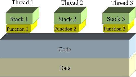
Threads are similar to processes in some ways however they share the same global/static data as well as the same code but have separate stacks.

threads1

Threads can be scheduled just like processes and so appear to operate in parallel – this is multi-threading.

threads2

Context switching

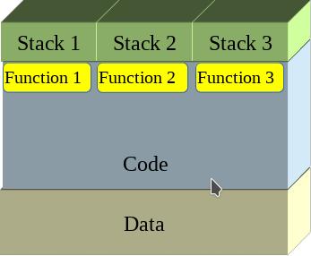
Each process or thread switch involves a context change: the current processor state (all of its register contents) must be saved and the processor state for the next thread or process loaded.  The image below illustrates a context change from Thread 1 to Thread 2

context_change

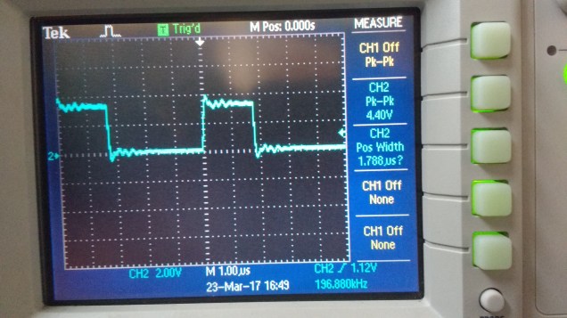
The context change is triggered by a timer interrupt and the ARM Cortex processors have a special timer aimed at just this role : the SysTick timer. In the following example the SysTick timer is configured to interrupt the CPU every millisecond which triggers a context change.

ARM Cortex M0 Exception handling

The following registers are placed on the interrupted thread stack (Process Stack) automatically following an interrupt (such as SysTick)

Address Contents
SP Prior to interrupt ????????
SP + 0x0000001C xPSR
SP + 0x00000018 PC
SP + 0x00000014 LR
SP + 0x00000010 R12
SP + 0x0000000C R3
SP + 0x00000008 R2
SP + 0x00000004 R1
SP + 0x00000000 R0

Why not save all of the registers? It is too slow (your ISR may not be changing all registers).

Why just these ones? R0-R3 typically are used for argument passing and should always be preserved by ISR’s. R12 is used by some compilers in their inner function call glue. The LR may hold a function return address. PC must be remembered so we know where to go back to and xPSR must be remembered for the flags.

For a full context switch, the remaining registers must be placed on the Process Stack also.

Address Contents
SP Prior to interrupt ????????
SP + 0x0000001C xPSR
SP + 0x00000018 PC
SP + 0x00000014 LR
SP + 0x00000010 R12
SP + 0x0000000C R3
SP + 0x00000008 R2
SP + 0x00000004 R1
SP + 0x00000000 R0
SP – 0x00000004 R11
SP – 0x00000008 R10
SP – 0x0000000C R9
SP – 0x00000010 R8
SP – 0x00000014 R7
SP – 0x00000018 R6
SP – 0x0000001C R5
SP – 0x00000020 R4

It is not possible carry this out in the C language so a little inline assembler is needed here to complete the context change.


// Preserve remaining registers on stack of thread that is being suspended (Thread A)
asm(" cpsid i "); // disable interrupts during thread switch
asm(" MRS R0,PSP "); // get Thread A stack pointer
asm(" SUB R0,#32"); // Make room for the other registers : R4-R11 = 8 x 4 = 32 bytes
asm(" STMIA R0! , { R4-R7 } "); // Can only do a multiple store on registers up to R7
asm(" MOV R4,R8 "); // Copy higher registers to lower ones
asm(" MOV R5,R9 ");
asm(" MOV R6,R10 ");
asm(" MOV R7,R11 ");
asm(" STMIA R0! , { R4-R7 } "); // and repeat the multiple register store
// Locate the Thread Control Block (TCB) for Thread A
asm(" LDR R0,=TCB_Size "); // get the size of each TCB
asm(" LDR R0,[R0] ");
asm(" LDR R1,=ThreadIndex "); // Which one is being used right now?
asm(" LDR R1,[R1] ");
asm(" MUL R1,R0,R1 "); // Calculate offset of Thread A TCB from start of TCB array
asm(" LDR R0,=Threads "); // point to start of TCB array
asm(" ADD R1,R0,R1 "); // add offset to get pointer to Thread A TCB
asm(" MRS R0,PSP "); // get Thread A stack pointer
// Save Thread A's stack pointer (adjusted for new registers being pushed
asm(" SUB R0,#32 "); // Adjust for the other registers : R4-R11 = 8 x 4 = 32 bytes
asm(" STR R0,[R1] "); // Save Thread A Stack pointer to the TCB (first entry = Saved stack pointer)

// Update the ThreadIndex
ThreadIndex++;
if (ThreadIndex >= ThreadCount)
  ThreadIndex = 0;

// Locate the Thread Control Block (TCB) for Thread B
asm(" LDR R0,=TCB_Size "); // get the size of each TCB
asm(" LDR R0,[R0] ");
asm(" LDR R1,=ThreadIndex "); // Which one is being used right now?
asm(" LDR R1,[R1] ");
asm(" MUL R1,R0,R1 "); // Calculate offset of Thread A TCB from start of TCB array
asm(" LDR R0,=Threads "); // point to start of TCB array
asm(" ADD R1,R0,R1 "); // add offset to get pointer to Thread B TCB
asm(" LDR R0,[R1] "); // read saved Thread B Stack pointer
asm(" ADD R0,#16 "); // Skip past saved low registers for the moment
asm(" LDMIA R0!,{R4-R7} "); // read saved registers
asm(" MOV R8,R4 "); // Copy higher registers to lower ones
asm(" MOV R9,R5 ");
asm(" MOV R10,R6 ");
asm(" MOV R11,R7 ");
asm(" LDR R0,[R1] "); // read saved Thread B Stack pointer
asm(" LDMIA R0!,{R4-R7} "); // read saved LOW registers
asm(" LDR R0,[R1] "); // read saved Thread B Stack pointer
asm(" ADD R0,#32 "); // re-adjust saved stack pointer
asm(" MSR PSP,R0 "); // write Thread B stack pointer

Threads are managed using a structure called a Thread Control Block which is defined as follows:


typedef struct {
uint32_t *ThreadStack;
void (*ThreadFn )();
uint32_t Attributes;
} ThreadControlBlock;
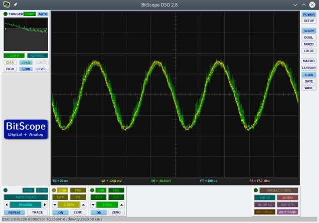
Implementation

A demonstrator application with three threads was developed for the Tiva C Launchpad.  Each thread flashes an LED on the board at a different rate.  The trickiest part to get right was the initial launching of the thread switching which involved a little bit of stack fiddling.  Code is available over here on Github

9 DOF on the STM32L476 Discovery board

The STM32L476 Discovery board has an LSM303 Accelerometer/Compass IC and an L3GD20 gyroscope attached to the MCU using an SPI bus and some chip select lines.  I wanted to experiment with them with a view to putting together a balancing robot.  Supporting code for the following was needed for this:

  • an SPI interface
  • the LSM303
  • the L3GD20
  • serial communications
  • periodic interrupts to pace data capture

Rather than build a complex Makefile I went with a simple shell script (or batch file if you prefer) with the following commands:

arm-none-eabi-gcc -static -mthumb -g -mcpu=cortex-m4 *.c -T linker_script.ld -o main.elf -nostartfiles
arm-none-eabi-objcopy -g -O binary main.elf main.bin

Note: your PATH environment variable must include the directory where arm-none-eabi-gcc is located.

The resulting main.bin file can then be copied to the virtual disk presented by the mbed interface on the STM32L476 discovery board.  (The program waits for you to press the centre joystick button before starting).`

Serial communications is carried out over the built-in ST-Link USB-Serial emulator so no additional hardware is needed (9600,n,8,1).

Code is available over here


Discovering the STM32L476G Discovery board

I have begun working the STM32L476 Discovery board taking a “Bare metal” approach.  It is a great board with some nice peripherals.  Code will be built up over time over here

To compile this code you need the a cross compiler for ARM that works on your system.  You don’t need a fancy debugger or complicated software : the board has an mbed interface so you can just copy the program you develop to the board as if it was a removable disk.

Sending encrypted data from an MSP432 to a python script

This post shows how you might send encrypted data over as serial communications port. The example was written for the MSP432 using the Energia environment. It uses AES128 ECB encryption using a pre-shared, hard coded (bad practice) key. The example generates a simple text message with a counter that counts from 0 to 255 repeatedly. The message is encrypted and sent as a HEX string (so I can read it) over a serial port. The receiver is a python script that decrypts the data and displays it to the screen. The code was developed in a Linux environment but should work fine in other operating systems – you will need to change the path for the serial port.
This example does not deal with the thorny issue of key distribution.
Energia code


#include <msp432.h>
#include <stdio.h>
/*   Serial communications with AES 128 ECB encryption
     Data sent in ASCII hex (e.g. the value 0x02 will 
     be sent as the string "02".  Transmitting in this 
     way allows us monitor the messages using a simple 
     serial monitor.  It also allows us use the 
     Serial.print and Serial.println methods without 
     worrying about data values that are zero (which 
     will be interpreted as end of string markers by the
     Serial library routines.  Of course this is less 
     efficient but it will hopefully be instructive.
*/

// Data block size (in bytes)
#define BLOCKSIZE 16

const char key[] = "8d2e60365f17c7df1040d7501b4a7b5a";
char plaintext[BLOCKSIZE]; 
///const char MSG[] = "Mary had a little lamb"; //  "Mary had a little lamb";
// the setup routine runs once when you press reset:
void setup() {
  Serial.begin(38400);
}
int Counter;
// the loop routine runs over and over again forever:
void loop() {
  sprintf(plaintext,"Counter=%d",Counter);
  Counter++;
  if (Counter > 255)
    Counter = 0;
  SendEncryptedMessage(plaintext, sizeof(plaintext) );
  delay(1000);
}

uint32_t ByteStringToNumber(const char *Str)
{
  uint32_t UpperNibble = 0;
  uint32_t LowerNibble = 0;
  if (Str[0] > '9')
    UpperNibble = (  Str[0] | 32 ) - 'a' + 10; // ensure lower case, remove hex 'a' and offset by 10
  else
    UpperNibble = ( Str[0] - '0');
  if (Str[1] > '9')
    LowerNibble = (  Str[1] | 32 ) - 'a' + 10; // ensure lower case, remove hex 'a' and offset by 10
  else
    LowerNibble = ( Str[1] - '0');
  return (UpperNibble << 4) + LowerNibble;
}
void setKey(const char * keystr)
{
  // The key will take the form of a 32 character ASCII string produced
  // by a tool like openssl.
  // This routine will extract the bytes from the string and store them
  // in the AES accelerator
  int Index;
  uint32_t KeySection;
  uint8_t *Ptr = (uint8_t *)(&AESAKEY);
  for (Index = 0; Index < 16; Index++)
  {
    KeySection = ByteStringToNumber(keystr + Index * 2);
    *Ptr = (uint8_t) KeySection;
  }
}

void SendEncryptedMessage(const char *Payload, unsigned int len)
{
  // Send the payload over the encrypted channel
  // Message is padded with zeros if it is not a multiple of BLOCKSIZE
  unsigned int BlockIndex = 0;
  unsigned int TotalByteCount = 0;
  uint8_t PlainTextBuffer[BLOCKSIZE];
  uint8_t CryptoText[BLOCKSIZE];
  volatile uint8_t *InputDataRegister;
  volatile uint8_t *OutputDataRegister;

  AESACTL0 = 0; // Set the AES engine into encryption mode
  setKey(key);  // Must set key after changing mode

  while (TotalByteCount < len)
  {
    BlockIndex = 0;
    while (BlockIndex < BLOCKSIZE)
    {
      if (TotalByteCount < len)
        PlainTextBuffer[BlockIndex] = Payload[TotalByteCount];
      else
        PlainTextBuffer[BlockIndex] = 0;
      BlockIndex++;
      TotalByteCount++;
    }
    InputDataRegister = (uint8_t *)&AESADIN;
    for (BlockIndex = 0; BlockIndex < BLOCKSIZE; BlockIndex++)
      *InputDataRegister = PlainTextBuffer[BlockIndex];
    delay(1);
    
    OutputDataRegister = (uint8_t *)&AESADOUT;
    for (BlockIndex = 0; BlockIndex < 16; BlockIndex++)
      CryptoText[BlockIndex] = *OutputDataRegister;

    for (BlockIndex = 0; BlockIndex < BLOCKSIZE; BlockIndex++)
    {
      if (CryptoText[BlockIndex] < 16)
        Serial.print("0"); // send leading zeros for values < 16
      Serial.print(int(CryptoText[BlockIndex]), HEX);
    }
      
    Serial.println(""); // Send a line feed after each block
  }

}

Python code

# This python script receives encrypted data over the serial port
# The encryption method is AES128, ECB and the key is hardcoded into
# sender and receiver
# Expected received data format:
# ASCII-HEX 32 characters (representing 16 bytes or 128 bits) followed by 
# CR LF (\r\n)

from Crypto.Cipher import AES
import serial as ser;
import binascii 
port=ser.serial_for_url("/dev/ttyACM0") # CHANGE THIS TO SUIT YOUR SITUATION!!!
port.baudrate=38400
key = binascii.unhexlify('8d2e60365f17c7df1040d7501b4a7b5a')
IV = 16 * '\x00' # set inital vector (or state) to 0
mode = AES.MODE_ECB # Electronic Code Book encryption used
encryptor = AES.new(key, mode, IV=IV)
while (1):
    ciphertext=port.read_until()
    if len(ciphertext)==34:      # got a full packet?
        ciphertext=ciphertext[:32] # trim off CR LF
        # convert to actual values rather than hex string
        ciphertext=binascii.unhexlify(ciphertext) 
        plaintext = encryptor.decrypt(ciphertext) # decrypt 
        print(plaintext) 

Energia and the MSP432 AES encryption engine

I’ve been trying to get matching results between the TI-MSP432’s encryption engine and a python equivalent on my laptop. It has been a bit frustrating but I think I’ve got it. The main cause of my frustration is that the AES registers are declared as if they represented 16 bit quantities and so the compiler was generating 2 byte writes to the registers. For example, the AESAKEY register is declared in msp432p401r_classic.h as follows:

#define AESAKEY (HWREG16(0x40003C06)) 

This messed up the engine’s state when I wanted to write bytes. Anyway, it works now and here is some Energia code that outputs the same answer as a python script (which is included in the comments). The code needs a little work and I hope to set up an encrypted link between the MSP432 and the PC over the UART.

#include <msp432.h>
/*key and message obtained from NIST test vectors in http://csrc.nist.gov/groups/STM/cavp/documents/aes/AESAVS.pdf */
/* Using AES 128 ECB Encryption */
/* Tested against the following python code:

# This produces the same answer as http://aes.online-domain-tools.com/
# but not the same as NIST test vector for ECB
from Crypto.Cipher import AES
import binascii
key = binascii.unhexlify('8d2e60365f17c7df1040d7501b4a7b5a')
IV = 16 * '\x00'
mode = AES.MODE_ECB
encryptor = AES.new(key, mode, IV=IV)
text = binascii.unhexlify('59b5088e6dadc3ad5f27a460872d5929')
#text=b'Plain text msg  '
ciphertext = encryptor.encrypt(text)
print(binascii.hexlify(ciphertext))

 */
const char key[]="8d2e60365f17c7df1040d7501b4a7b5a";
const char testmsg[]="59b5088e6dadc3ad5f27a460872d5929";
uint32_t ByteStringToNumber(const char *Str)
{
  uint32_t UpperNibble = 0;
  uint32_t LowerNibble = 0;
  if (Str[0] > '9')
    UpperNibble = (  Str[0] | 32 ) - 'a' + 10; // ensure lower case, remove hex 'a' and offset by 10
  else
    UpperNibble = ( Str[0] - '0');
  if (Str[1] > '9')
    LowerNibble = (  Str[1] | 32 ) - 'a' + 10; // ensure lower case, remove hex 'a' and offset by 10
  else
    LowerNibble = ( Str[1] - '0');
  return (UpperNibble << 4) + LowerNibble;
}
void setKey(const char * keystr)
{
  // The key will take the form of a 32 character ASCII string produced
  // by a tool like openssl.
  // This routine will extract the bytes from the string and store them
  // in the AES accelerator
  int Index;
  uint32_t KeySection;
  uint8_t *Ptr = (uint8_t *)(&AESAKEY);
  Serial.println("Setting the following key: ");
  for (Index = 0; Index < 16; Index++)
  {
    
    KeySection = ByteStringToNumber(keystr+Index*2);
    Serial.print(KeySection,HEX);
    Serial.print(" ");
    *Ptr = (uint8_t) KeySection;   
    
  }
  Serial.println("");
  printAESRegisters();
}
void encryptBlock(const char *plain_text, char *crypto_text, uint32_t len)
{
  // Encrypts a 128 bit (16 byte) block of text
  int Index = 0;
  uint8_t Dummy = 0;
  uint32_t Section;
  volatile void *Ptr;
  // select encrypt mode  
  AESACTL0 = 0;//0xfffc;
  setKey(key); 
  Ptr = &AESADIN;
  Serial.println("Encrypting the following:" );
  for (Index = 0; Index < 16; Index++)
  {

    Section = ByteStringToNumber(plain_text+Index*2);
    Serial.print(Section,HEX);
    Serial.print(" ");
    *((uint8_t *)Ptr) = (uint8_t)Section;   
  }
  Serial.println(" ");
  delay(4);
  //while ( (AESACTL0 & (1 << 8) )==0); // wait for ready flag
  Ptr = &AESADOUT;
  for (Index = 0; Index < 16; Index ++)
  {
      crypto_text[Index] =  *((uint8_t *)Ptr);      
  } 
}


void printAESRegisters()
{
  Serial.print("AESASTAT: ");
  Serial.print(String(AESASTAT,16));
  Serial.print(", AESACTL0: ");
  Serial.print(String(AESACTL0,16));
  Serial.print(",  AESACTL1: ");
  Serial.println(String(AESACTL1,16));
}


// the setup routine runs once when you press reset:
void setup() {
  Serial.begin(38400);
}
char CryptoText[17];  
// the loop routine runs over and over again forever:
void loop() {
  int Index;
  CryptoText[16]=0;
  AESACTL0 = 0;
    
  encryptBlock(testmsg,CryptoText,16);  
  Serial.println("Just encrypted");
  printAESRegisters();
  Serial.println("Crypto Text:");
  
  for (Index = 0 ; Index < 16; Index ++ )
  {
    Serial.print(int(CryptoText[Index]),HEX);    
    Serial.print(" ");
  }
  Serial.println(" ");
  Serial.println(CryptoText);
  Serial.println("--------------------------------");

  delay(501);
}

Command line compiling

A student asked how to use the standard C libraries with one of my examples recently. He wanted to know how to use string functions such as strcat, strcpy and so on. This isn’t something I had tried before because my goal was to expose the lower level details of hardware I/O. Anyway, having fiddled around a bit on the command line I came up with this command for buidling code for the STM32L011 nucleo board

arm-none-eabi-gcc -static -mthumb -mcpu=cortex-m0plus main.c init.c serial.c -T linker_script.ld -o main.elf -nostartfiles

Breaking this down:
arm-none-eabi-gcc: Your cross compiler. Your PATH environment variable should include the directory this lives in.
-static: Don’t use DLL’s (run-time linking) i.e. include the library function code in the final executable image.
-mthumb: Generate thumb code rather than ARM code.
-mcpu=cortex-m0plus: The STM32L011 has a Cortex M0+ CPU
The list of C files
-T linker_script.ld: Use this linker script to define memory regions when building the output executable image.
-o main.elf: name the output file main.elf
–nostartfiles: Don’t include “standard” start and stop functions. The code includes our own custom start-up code

I wanted to be able to dump the output file onto the virtual disk emulated by the nucleo board. This is done as follows:

arm-none-eabi-objcopy -O binary main.elf main.bin

This creates a raw binary program image which can be dropped on to the virtual disk.
The code was based a previous serial example for the STM32L011. The main.c file is replaced with this:


/* 
 * Serial: serial i/o routines for the STM32L011
*/


#include "stm32l011.h"
#include "serial.h"
#include <string.h>
void delay(int);

void delay(int dly)
{
  while( dly--);
}

void initClockHSI16()
{
    // Use the HSI16 clock as the system clock - allows operation down to 1.5V
        RCC_CR &= ~BIT24;
        RCC_CR |= BIT0; // turn on HSI16 (16MHz clock)
        while ((RCC_CR & BIT2)==0); // wait for HSI to be ready
        // set HSI16 as system clock source 
        RCC_CFGR |= BIT0;
}
void configPins()
{
	// Enable PORTB where LED is connected
	RCC_IOPENR |= BIT1;
	GPIOB_MODER |= BIT6; // make bit3  an output
	GPIOB_MODER &= ~BIT7; // make bit3  an output
}	
const char Str1[]="Hello ";
const char Str2[]="World\r\n";
char CombinedString[50];
int main()
{
        uint32_t Counter=0;
	initClockHSI16();
	configPins(); 
        initUART(9600);
	CombinedString[0]=0;
        CombinedString[49]=0;
        
	while(1)
	{
		GPIOB_ODR |= BIT3;
		delay(2000000);
		GPIOB_ODR &= ~BIT3;
		delay(2000000);
                strcpy(CombinedString,Str1);           
                strcat(CombinedString,Str2);
                eputs(CombinedString);                
                eputs("\r\n");                
	} 
	return 0;
}