Assembly instructions.
Step 1: Wires and resistors
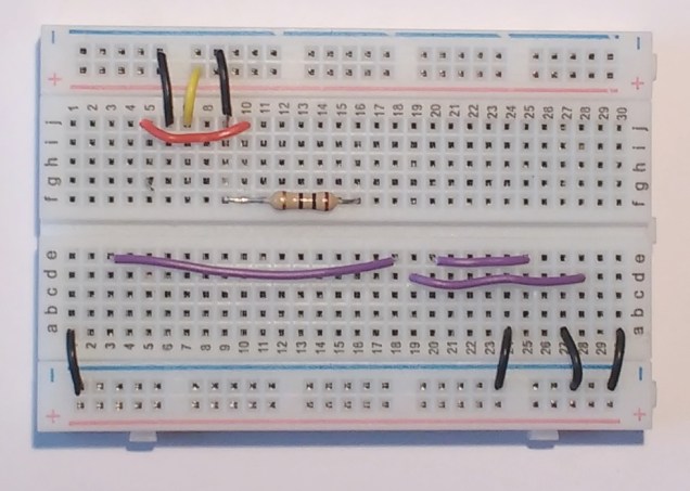
Notes
Not the orientation of the board (red line at the bottom).
Pay attention to the numbering of rows and columns.
Stick with the colour code.
Step 2: Buttons and buzzers
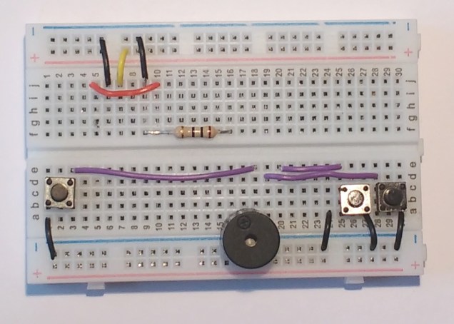
Notes
The buzzer’s ‘+’ pin should be pushed in to row ‘a’, column 17. The other pin goes in to any hole just below the blue line.
Step 3: The battery pack
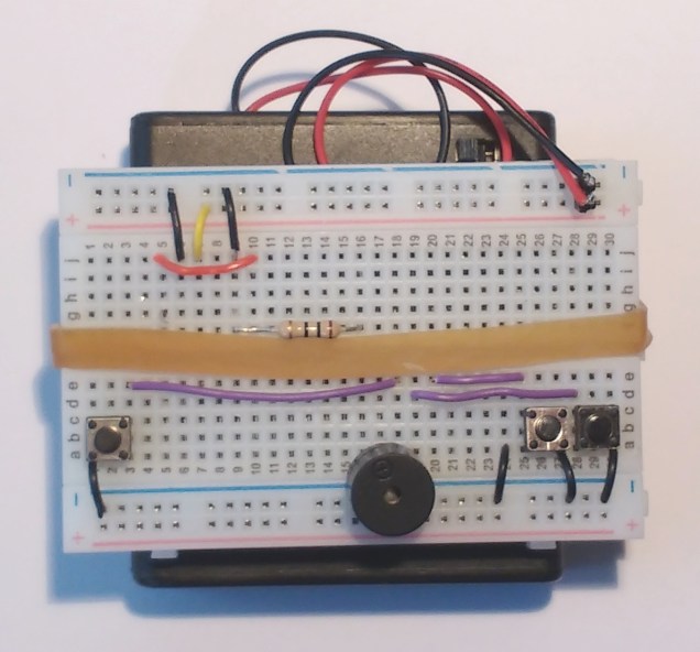
Notes
Pay close attention to the connection of the red and black wires to the breadboard. The black wire goes beside the upper blue line and the red wire goes beside the upper red line.
The switch should be accessible just above the breadboard.
Tuck any extra wire in between the breadboard and the battery case.
Make sure the battery switch is in the OFF position.
Step 4: The CPU board
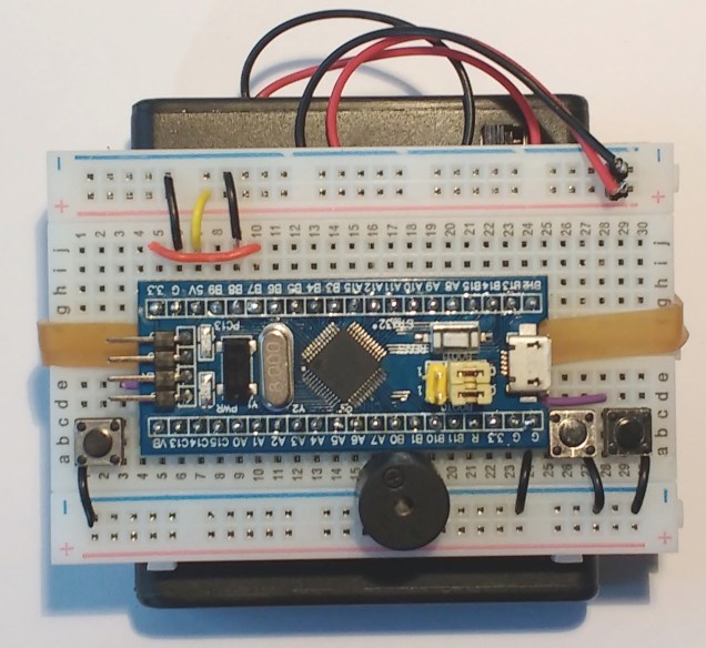
Notes
It is very important to put this in to the correct holes on board. The bottom left pin labelled VB should go in to row c, column 5
Step 5: The display
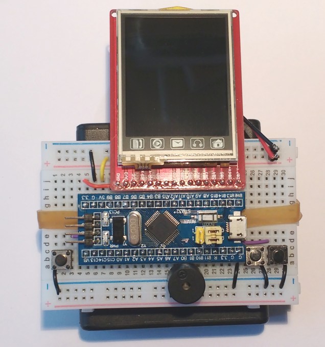
Notes
Once again, the placing of the screen is very important. Its right-most pin labelled DB7 should go in to row i, column 24.
Turn it on and play!
Source code.
