
Assembly instructions
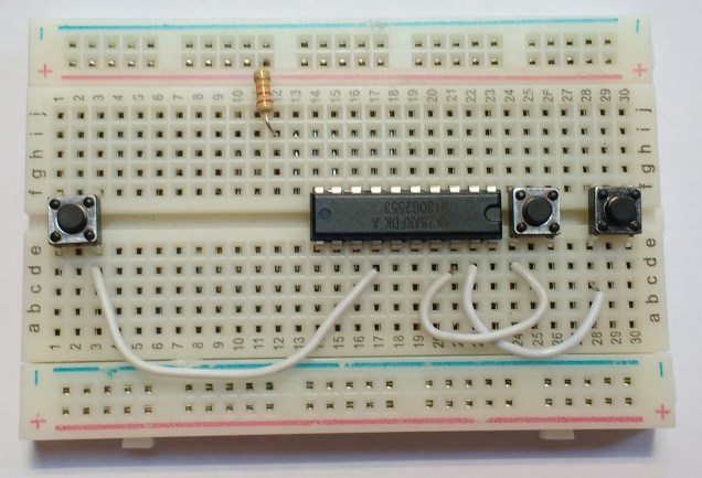
MCU, buttons and reset resistor

Note the orientation of the breadboard!
The MCU (Microcontroller Unit) is a little computer that runs the game. The program has been placed in its memory already. Put the components in as shown:
The buttons – place the bottom left pin of the buttons as follows:
Left button: Row e, Column 1
Fire button: Row e, Column 24
Right button: Row e, Column 28
The MCU – Note the location of the dimple on the right of the image.
MCU: Bottom left pin: Row e, Column 14
The resistor : Bottom leg – Row i, Column 12; Top Leg – anywhere in the upper red row
The white wires
The white wires connect the MCU to the buttons.
Wire 1: Row d, Column 3 to Row d, Column 17
Wire 2: Row d, Column 21 to Row d, Column 24
Wire 1: Row d, Column 22 to Row d, Column 28
Yellow and green wires

The yellow wires carry some of the signals from the MCU to the display. The MCU also connects to some of the display pins directly as you will see later. The green wire is used to carry a Reset signal to the MCU
Yellow wire 1: Row f, Column 8 to Row d, Column 14
Yellow wire 2: Row f, Column 9 to Row d, Column 15
Yellow wire 3: Row f, Column 10 to Row d, Column 16
Green wire: Row f, Column 12 to Row d, Column 19
Red and black wires
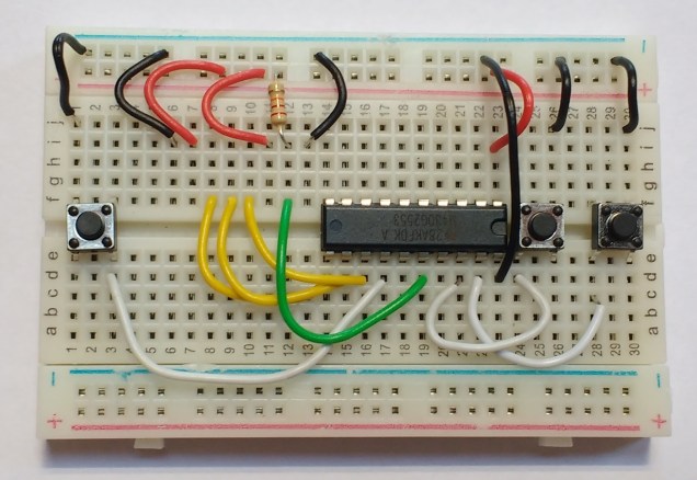
The red and black wires connect various parts of the circuit to the battery.
Short black wire 1: Row j, Column 1 to upper blue row
Short black wire 2: Row i, Column 6 to upper blue row
Short black wire 3: Row i, Column 13 to upper blue row
Short black wire 4: Row j, Column 26 to upper blue row
Short black wire 5: Row i, Column 30 to upper blue row
Long black wire : Row d, Column 23 to upper blue row
Red wire 1: Row i, Column 7 to upper red row
Red wire 2: Row i, Column 11 to upper red row
Red wire 3: Row i, Column 23 to upper red row
The display and the battery pack

Putting the LCD display in can be a little difficult. Make sure the breadboard is on a flat surface before you start. Carefully ease the display into the board as shown – this will require a little force. Make sure you line it up in the right row/column first.
Display : Left pin (GND) : Row h, Column 6
The battery pack supplies 3V to power the display and the MCU. The black wire from the battery can go into any column along the upper blue row. The red wire goes in to any column in the upper red row.
Turn on the battery pack and have fun!
Source code for the games is available over here on github
